VRC Documentation
Introduction
Installing or Upgrading VRC
What's New
Running VRC for the First Time
A Tour of the VRC Primary Display
The Profile System
Color Profiles
Configuring VRC (General Settings)
Configuring Sounds
Configuring Audio Devices
Calibrating Your Microphone
Configuring the Scope
The Weather Panel
The Controller List
The Aircraft List
The Comms Panel
The SELCAL Panel
The Incoming Chat Log
Setting your ATIS
Connecting to VATSIM
Navigating the Scope
The Various Radar Modes
Opening Additional Displays
Selecting Aircraft
Working With the Command Line
Chat Windows
Communicating with Pilots
"Tagging-up" an Aircraft
Viewing & Editing Flight Plans
Assigning a Squawk Code
Assigning Temp and Cruise Altitudes
Setting the Scratchpad
Setting the Voice Type
Tracking Targets
Handoffs
Pointing Out an Aircraft
Ground-to-Ground Communications
The Right-Click Menu
The Flight Strip Bay
The Oceanic Tracks Window
Conflict Alerts
The Virtual Tower View
Some Useful Tools
Advanced Topics
Appendix A - Command Reference
Appendix B - Files in the VRC Folder
Appendix C - Contents of a Profile
Appendix D - Error Messages
Appendix E - The VRC End-User License Agreement
Appendix F - The .sct2 Sector File Format
Appendix G - Sector File Formatting Requirements
Introduction
What is VRC?
VRC stands for Virtual Radar Client. VRC is used to connect to the VATSIM Virtual Air Traffic SIMulation network. VRC simulates the radar system used by air traffic controllers to guide aircraft along their routes through the simulated world on VATSIM. VRC is developed by Ross A. Carlson, a controller and instructor in the VATSIM Boston ARTCC. (ZBW) Portions of VRC (mainly the underlying networking and voice libraries) were contributed by Chris Serio and Ben Supnik, also of the virtual Boston ARTCC.
Development of VRC began in April of 2005. Phase one of the closed beta test began in November of 2005. Phase two began in March of 2006, and VRC was released in April of 2006.
Why Make Another ATC Client?
VATSIM began with ProController, which was then replaced by ASRC. ASRC is a fantastic program with many great features and excellent reliability. VRC was developed as an alternative to ASRC, primarily for users with multiple-monitor computer systems. VRC also takes a slightly different approach in terms of its user interface. Where ASRC strives to more closely model real-world radar systems, VRC was designed more for ease of use in the simulated radar environment found on VATSIM. Realism is a secondary concern, instead of a primary design goal.
Single vs. Multiple Monitor Support
As mentioned above, VRC is design for use on multiple-monitor systems. The goal is to keep the primary radar screen as uncluttered as possible. This is achieved by moving all secondary functions to floating tool windows which are intended to be dragged onto a side monitor. These secondary functions include flight strip editing, chat, communications control, the controller list, the arrival/departure list, etc. The only items that are kept on the main screen are those that the controller interacts with very often, such as the radio text area, the command line, and current weather information.
Because of this design approach, many users with single monitors may find the VRC interface quite "stuffy" or uncomfortable. It is possible that a future version of VRC may bring a more single monitor friendly version of the interface, but there are no such plans as yet.
Major Differences From ASRC
Following are the most notable areas where VRC differs from ASRC:
- Numerous Floating Windows - As mentioned above, most secondary functions in VRC have been relegated to floating "tool windows" which the user can position anywhere on the screen. These are intended to be positioned on a side monitor, freeing up screen real estate for the primary scope. ASRC integrates all of its functionality into the main screen.
- The Button Bar - Across the top of the main scope you'll find the Button Bar. This area contains various buttons which offer quick access to certain pieces of information or certain actions. This feature is vaguely similar to the buttons seen across the top of real-world STARS scopes. This feature is listed in this section because it represents a significant user interface difference between VRC and ASRC.
- Communications Management - ASRC has a feature called the VSCS (Voice Switching and Communications System) which models its real-world counterpart. The VSCS contains buttons for both air-to-ground and ground-to-ground communications. VRC has no such device. Air-to-ground communications in VRC are handled through the Comms Panel. Ground-to-ground communications are only accesssible through dot commands.
- The Profile System - VRC includes a system where the user can save different configurations as a "profile" and quickly restore any such configuration by way of the Profile Selection window. ASRC users can achieve similar functionality through a third-party program called ASRC Configurator.
Assumptions
In order to fully understand the concepts laid out in the manual, you should have at the very minimum: knowledge of basic Air Traffic Control terminology and procedures, as well as access to the sector files, alias files and POF files used in the area where you intend to control. Check with the Air Traffic Manager or training staff in your area in order to acquire the necessary files and information.
Installing or Upgrading VRC
Requirements
VRC has the following hardware & software requirements:
- Windows 2000 or Windows XP (Other Windows versions are untested)
- Video card with OpenGL support with current drivers
- Any Windows-supported sound card with current drivers
- Internet connection with reasonable latency (modem is sufficient)
- Headset/speakers & microphone if using voice
VRC makes use of the following network ports:
| Port | Protocol | Data Type | Notes |
| 6809 | TCP | Aircraft position updates and general network data | Outgoing - generally no forwarding needed. |
| 3782 | TCP | Voice communications | Outgoing - generally no forwarding needed. |
| 3290 | UDP | Voice communications | MUST be forwarded through your router! |
Note that only port 3290 UDP must be forwarded through your router for incoming connections. The other two ports are for outgoing connections only.
Installing for the first time
After downloading VRC, you will have a file named "VRCInstaller.exe" or perhaps just "VRCInstaller" depending on your Windows Explorer settings. Run this program to start the VRC installation. You will be prompted to accept the VRC End-User License Agreement before you can continue the installation. After accepting the EULA, you will be given some options to how VRC is installed:
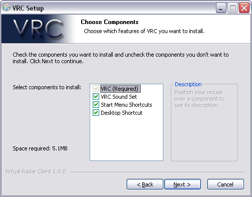
The first option is obviously required and cannot be unchecked. That option simply installs the main VRC executable file.
If you select the second option, "VRC Sound Set", then a set of default sound files will be installed in a "Sounds" folder within your "My Documents\VRC" folder. These sounds will also be configured automatically within the "Default" profile. (See "The Profile System") You can always change the sounds later if you wish.
The last two options allow you to choose whether or not you want the installer to create a shortcut on your desktop and/or in your Start Menu under "All Programs".
The next screen allows you to choose the folder where you wish to install VRC:
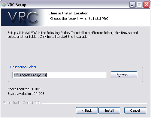
Simply type the location you want to use, or click the "Browse..." button and select a folder on your hard drive. After choosing the installation folder, press the "Install" button and VRC will be installed.
Upgrading to a new version
Upgrading VRC is essentially the same as installing. There is no need to uninstall VRC first. Simply download the installer for the latest version and run it. It will overwrite the existing version, while keeping your configuration intact. (It will not overwrite an existing VRC.ini file, which is where your profiles are stored.)
When upgrading to version 1.2, your INI file will undergo a conversion process the first time you run version 1.2. Starting with version 1.2, all color selections are stored in Color Profiles which are new bracketed sections in the INI file. Color profiles based on your existing color selections will be created when you first run version 1.2.
Uninstalling
There are two ways to uninstall VRC. Assuming you allowed the installer to create Start Menu shortcuts, you will find an Uninstall option in the VRC folder in your Programs Menu. The other method is to access the "Add or Remove Programs" option from your Windows Control Panel. Select the VRC entry from the list and press the "Remove" button.
The following actions are taken when the VRC uninstaller is run:
- The VRC.exe file is deleted.
- Support files are deleted from the folder where you installed VRC. These files include uninstaller.exe, servers.txt, VRC_EULA.txt, and VRC_sector_parse_results.txt.
- The Start Menu and Desktop shortcuts (if any) are removed.
- VRC is removed from your "Add or Remove Programs" list.
Note that your VRC.ini file (where all your profiles are stored) is not deleted. It will remain on your hard drive in case you decide to reinstall VRC in the same location. All other files remain untouched as well, such as any sector files, alias files, or sound files that you may have added.
What's New
Version 1.2
The most significant additions in VRC 1.2 are certainly the Voice ATIS functionality and the new color profiles. Following is a full list of new features:
- Voice ATIS. You can now record a voice ATIS message and have it broadcast on a separate frequency and voice channel.
- Your text ATIS is now managed entirely within the ATISMaker window ... there is no longer a text ATIS box in the General Settings.
- Color Profiles allow you to define a set of color selections and then assign them to each scope window independently, allowing for ultimate flexibility in scope color configuration.
- New checkbox options for automatically adding, deleting, and pushing flight strips.
- New command for tagging up all aircraft owned by a specified controller. See the Command Reference for details.
- New command to reload the current sector file. This is useful for sector file authors while making changes and tweaks to the sector file.
- VHF simulation option for headset and speakers. This makes pilots more understandable when using speakers or headphones with lots of bass.
- Tabbed interface in general settings. The settings are now much easier to find and are less cluttered.
- Show aircraft route with waypoints. CTRL-F6 now shows the aircraft route, and displays the labels for all known waypoints on the route.
- Separation links allow you to link two or more aircraft together and see the separation between them, updated in real time.
- "Realistic Tags Mode" prevents you from seeing a full data tag for aircraft not squawking their assigned beacon code.
- Quicklook feature allows you to temporarily tag up all aircraft on the scope. There is a new button in the button bar to toggle this feature.
- Sticky Notes. You can now place a sticky note containing any text, anywhere on the scope. Sticky notes can be dragged to a new location as desired, even to a different scope.
- Aircraft info lookup. A new dot command allows you to look up information about a selected aircraft, such as engine type, number of engines, weight class, SRS category, etc.
- Flight strip annotations are now preserved when pushing a strip to another VRC user.
- The new incoming chat log shows all incoming chat messages in a single box, without having to open the chat window for each sender.
- Current oceanic tracks can now be downloaded from the web and plotted on your scope.
- Each scope can now have its own airspace floor and ceiling filters defined.
- Each scope can also have a defined radar floor, below which no targets will be shown, regardless of your filter settings.
- Scratchpad presets. You can now define a list of preset scratchpad entries, and select them from a list in the aircraft right-click context menu.
- STARS radar mode. VRC now simulates the STARS radar system used in many TRACONS and Towers in the United States.
- The aircraft's weight class (heavy, etc) is now shown in the target data block where appropriate.
- Entries in the Controller List and Arrival/Departure list are now be grouped with section headers. These can be disabled in the Controller List.
- The /v voice tag is now hidden, as it is the most common case. Only the /t and /r tags are shown. If the voice type is unknown, /? is shown.
- Chat and radio history can now be timestamped.
Version 1.2 also includes numerous tweaks to existing features, as well as bug fixes.
Version 1.1
The most significant additions in VRC 1.1 are certainly the Virtual Tower View and the new radar modes. (Simple, Park Air, TAAATS, PSR, and 3D) Following is a full list of new features:
- Virtual Tower View. VRC can now create an MSFS multiplayer session and populate it with aircraft. By connecting FS9 to this session, you can have a realistic "out-the-window" view of the airport environment.
- Simple radar mode. This mode is what used to be called the Ground mode in version 1.0.
- Ground radar mode. This is a new mode which shows the callsign, aircraft type, and ground speed.
- Park Air radar mode. This mode emulates the approach control radars used in the United Kingdom.
- TAAATS radar mode. This mode emulates the TAAATS system used within and around Australia.
- PSR radar mode. This mode provides basic "skin paint" primary radar targets without SSR information.
- 3D radar mode. This unique mode provides a 3D "wire frame" view of your airspace, with targets represented as basic 3D models.
- Colorized sector areas. VRC now supports the ability to draw filled, colored polygons on the screen, to represent airways, special-use airspace, bodies of water, etc. This is also useful for creating ground radar maps. These polygons, referred to as "REGIONs" are available in .sct2 format sector files.
- Static text labels. You can now define simple lines of text to display on your scope at a specified lat/lon. This is useful for labeling items such as taxiways, MVA values, special-use airspace names, etc. These labels are available in .sct2 format sector files.
- F2 <ASEL> allows you to quickly add a weather button for the destination field for the selected aircraft. This is handy when controlling aircraft flying into satellite fields, so that you can quickly pull up the weather and monitor altimeter changes.
- The new .center2 command allows you to quickly center both your scope and the range rings at the specified point.
- Right-click context menus. Most areas in VRC now have right-click context menus, allowing you to quickly access important functions with only the mouse. For example, by right-clicking a target on your scope, you can quickly initiate a handoff to another controller. Right-click context menus are available for targets on the scope, entries in the arrival/departures list, entries in the controller list, entries in the weather panel, entries in chat group member lists, and flight strips.
- Profile import/export. You can now easily share profiles and common settings using the profile import, export and merge functions.
- Reminder lights. A new button in the button bar contains four reminder lights. These lights remind you if you have a chat message waiting, a pending handoff, aircraft in your reminder list, or if your microphone is muted.
- Tool window hotkeys. Using the Alt key plus a number, you can quickly show or hide the various tool windows. See the Command Reference for details.
- The new CTRL+G key combination provides quick access to the Diagrams Window for the currently active scope.
- Callsigns in the reminder list are now sorted by how long they have been on the list, so you can quickly see which aircraft has been waiting the longest.
- The SELCAL window. VRC now provides a window listing all aircraft in range which have a SELCAL code in their flight plan remarks. By double-clicking an entry in the list, you can quickly send a SELCAL alert to the specified aircraft.
- Mutable microphone. You can now mute your microphone if you don't wish to have a hot microphone when being overridden.
- The new .fd command allows you to use aliases to toggle diagrams on/off.
- Session statistics. VRC now keeps track of various operational statistics during your session. You can view these stats with the .showstats command.
- New alias variables and functions. You can now insert additional data in an alias. The new variables and functions include $atiscode, $type(), $route and $aircraft.
Version 1.1 also includes numerous tweaks to existing features, as well as bug fixes.
Running VRC for the First Time
The Default Profile
When you run VRC, the first thing you see is the Profile Selection Window. The first time you run VRC, the profile list will contain only the "Default" profile, as shown here:
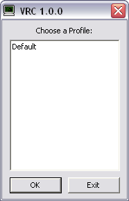
Once you have configured VRC and created one or more profiles (see "The Profile System") those profiles will be listed in the Profile Selection Window as well. Since this is your first time running VRC, you will obviously have to start with the Default profile. Select the Default profile either by double-clicking on the entry in the list, or by clicking it once then pressing Enter or clicking the OK button.
After loading the Default profile, you will see a single Display window (the scope) on your primary monitor. No other windows will be loaded for now. Also, this Primary Display will not have any sector data loaded yet. You will also see a reminder message telling you to specify a POF file. See below for more information on initial configuration.
What VRC Does at Startup
After selecting a profile, VRC does two things before allowing you to continue:
- Downloads the server list
- Performs a version check
When VRC downloads the server list, it makes a web connection to the VATSIM data servers in order to fetch a list of currently available servers for you to connect to. This usually takes about 5 or 6 seconds to complete. If you are running a firewall, you may be prompted to allow VRC to access the internet. You will have to allow this in order to use VRC.
After downloading the server list, VRC then makes another web connection to the VRC web site in order to confirm that you are running the latest version. If you are not, then you will see a message showing that there is a new version available. When you see this message, you should visit the VRC website and download the new installer.
If either the server list download or the version check fails, you may see an error displayed at the bottom of the scope. Normally you can continue to use VRC if the server download fails, but only if it has succeeded at least once previously. This is because each time the server list is downloaded, it is cached on your hard drive. This allows VRC to load the last successfully-downloaded server list in case the download fails.
It's fine if the version check fails as that will not prevent you from using VRC.
Loading a Sector File
The first thing you should do is load a sector file. You can usually get sector files from the website for the area where you will be controlling. Download the sector file and save it in the "My Documents\VRC" folder. (You can save the sector file anywhere you like, but it's easiest if they are in the "My Documents\VRC" folder so that you don't have to dig for them later when you actually load them.) Then, select "Open Sector..." from the "File" menu. In the window that opens, double-click the sector file. The sector file may take a few moments to load, depending on the speed of your computer and the size of the file. After it is done loading, you will see the sector information on your Primary Display. You can experiment with the options in the "View" menu in order to turn various pieces of sector data on and off.
Initial Configuration
Once a sector file is loaded, you could connect and start controlling right away, but there are a few items you'll want to configure first in order to be able to use all of VRC's features. The first such item is your key configuration. This includes your Push-to-talk (PTT) key and your Aircraft Select (ASEL) key. The PTT key is used when transmitting your voice either to pilots or other controllers via a "land line" connection.
In order to configure these keys, open the "Settings" menu and choose "General...". This will open the main VRC General Settings window. Select the "Hotkeys" tab:
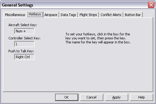
To set the key, click in the box, then press the key you wish to use. The name of the key will be shown in the box. Be sure to use a key that you will not be needing for any other reason while using VRC. The default settings are usually best if you haven't used VRC or ASRC before. Press the "Apply" button to save your hotkey settings.
Other items that you should configure right away include:
- POF file
- Alias file
- Arrival & Departure field lists
- ATIS
See the section on Configuring VRC for details on how to configure these items.
Connecting to VATSIM
Once you have completed the basic configuration, you are ready to connect to VATSIM. To do so, choose "Connect..." from the "File" menu. You will then see the Connect Window:
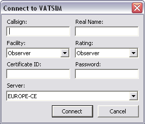
First, fill in your chosen callsign. The first time you connect, while you are getting used to the VRC interface, you should connect as an Observer, so choose an appropriate Observer callsign. Usually, the staff for the area where you will be controlling will have policies on how you should format your callsign when connecting as an Observer. For example, at the Virtual Boston ARTCC (ZBW), I would use "BOS_CN_OBS". The first three letters are the airport identifier, the second two letters are my operating initials, and the last three letters obviously identify you to the network as an Observer. Observer callsigns should always end in "_OBS".
Next, fill in your Real Name. This is required to be accurate in order to comply with VATSIM policies.
Next, select the facility type you will be connecting as. The first time you connect, you should leave this as "Observer".
Next, select your VATSIM rating from the "Rating" dropdown list. If you have not yet attained any ratings as a controller, you will need to select "Observer". The VATSIM servers will not allow you to connect unless you choose the correct rating from this list.
Next, enter your VATSIM CID and Password. These are normally numeric, at least 6 digits each. You get them when first registering on VATSIM.
Next, select the appropriate server from the "Server" dropdown list. Choose a server that is "geographically close" to your real-world location. All of the servers are interconnected, so you will be able to "see" any controllers or aircraft within range regardless of which server they choose to connect to.
Finally, press the "Connect" button. The Connect Window will close, and VRC will attempt to connect to the VATSIM network using the information you just provided. Text messages will be shown in the Primary Display telling you whether or not the connection succeeded. Normally, the connection will happen instantly, and you will see some welcome messages from the server. The Primary Display title bar will also be updated to show which server you are connected to.
You are now connected to VATSIM!
Creating Your First Profile
Once you have gone to all the trouble of configuring the above items, you won't want to have to do it all over again the next time you use VRC, so you should save your settings in a session profile. To do so, choose "Save Session Profile As..." from the "File" menu. You will be prompted to enter a name for your session profile. Since this first profile is just for observing, you should give it a name that identifies it as such. For example, if you are observing at KBOS, a good name for the session profile might be "Boston Observer".
After you type in a name and press Enter, VRC will save the session profile in your VRC.ini file. The next time you start VRC, this new profile will be listed in the Profile Selection Window, allowing you to quickly re-load these settings.
For details regarding creating and using session profiles, see "The Profile System".
Disconnecting From VATSIM
When you are ready to disconnect from the network, choose "Disconnect" from the "File" menu. You will be prompted to confirm that you really wish to disconnect (this prompt can be disabled in the General Settings) and then your connection will be closed, assuming you confirm the disconnect. A message will be shown in the Primary Display showing that you are no longer connected. The title bar will be updated as well.
Closing VRC
When your VRC session is over, you can close VRC by either clicking on the standard window close button (usually an X in the upper right corner) in the Primary Display, or by choosing "Exit" from the "File"menu. If you are still connected to VATSIM, you will be prompted to confirm that you really wish to disconnect. If you have unsaved changes in your session profile, you will also be prompted to save the profile before closing VRC. Both of these prompts can be disabled in the General Settings.
A Tour of the VRC Primary Display
Refer to the following screenshot while reading this section:
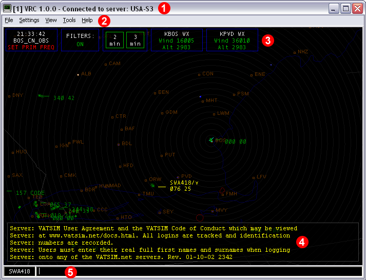
1) The title bar
The very top of each display contains a standard Windows title bar. This text in the title bar shows three pieces of information. The first is the Display Number for this display. This is obviously always "1" for the Primary Display. As you open Secondary Displays, they will each be assigned a sequential number which will appear in the title bar. This number is used for sending commands to specific displays. (See "Opening Additional Displays" for details.)
The next piece of info shown in the title bar is the current VRC version number, for your reference.
Finally, your connection status is shown. This will either say that you are not connected, or it will show the name of the server to which you are connected.
2) The menu bar
This is a standard Windows menu bar. The items in the menu bar vary depending on if you are looking at a Primary Display or a Secondary Display. For Primary Displays, the following menus are available:
- File
- Settings
- View
- Tools
- Help
For secondary displays, only the following menus are available:
- File
- Settings
- View
Also, the options available in each of these menus vary depending on if you are looking at a Primary Display or not. For Secondary Displays, only those options that pertain to the configuration of that Display are shown. None of the "main" functions such as Connect/Disconnect, profile options, etc. are available on the Secondary Display menu bars.
Most of the various menu items are described in detail in the pertinent sections of this User Manual. The exception is the "Help" menu. This menu contains links to various sections of the VRC web site. The "About VRC" option simply opens a small window showing your current version and some development credits.
3) The Button Bar
The Button Bar contains various buttons which provide quick access to certain VRC functions. The buttons you see in the Button Bar vary depending on how you have VRC configured, among other things. Following are examples of all possible buttons that may appear in the Button Bar during your VRC session:
|


Descriptions of most of these buttons and their functions can be found within the pertinent sections of this User Manual. Some are described here:
The reminder lights button contains four small lights which blink to remind you of various important items. If the H light is blinking, that means another controller has handed an aircraft off to you and you haven't yet accepted the handoff. If the M light is blinking, that means your microphone is muted. If the C light is blinking, that means you have an unread chat message. And if the R light is blinking, that means you have one or more aircraft on your reminder list.
The quicklook button tags up all aircraft which are not already tagged up. This is so you can quickly see the callsign and other information for aircraft not under your control.
4) The Radio History area
This portion of the Display is referred to as the Radio History area, though displaying radio text is only its primary function. In addition to text messages sent to or received from aircraft, the Radio History area also contains any other messages that you receive during your VRC session, other than chat. These include ATC messages, server messages, broadcasts, error messages, and confirmation messages sent as a result of you performing some action within VRC.
The size of the Radio History area can be adjusted via key commands. See "Communicating With Pilots" for details.
5) The command line
The command line is where you will enter all commands for working with aircraft, configuring your scope, etc. See "Working with the command line" for more information.
The Profile System
Loading a Session Profile
When you first run VRC, you will see the Profile Selection Window. This window lists all of your various saved session profiles. When you choose a session profile, all of the settings that were in effect when you created or last update the profile will be restored, and the various Display Windows and Tool Windows will be opened and positioned in the same location where they were when you last saved the profile. Here's an example screenshot of the Profile Selection Window:
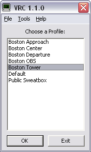
Notice that the "Boston Tower" session profile is currently selected. This is because the profile that you used last is automatically selected when you view the Profile Selection Window. In order to use the selected profile, you can simply press Enter. To select any other profile, you can use the arrow keys or click on the profile name in the list. You can also type the first few letters of the profile and the selection will change as you type. You can then open the selected profile by pressing Enter, by pressing the "OK" button, or by double-clicking the entry in the list.
You can also click the "Exit" button or press Esc if you just want to close the Profile Selection Window without actually starting VRC.
Creating a New Profile
To create a new profile, you must first load an existing profile. Load the profile that most closely matches the profile that you want to create. After loading a profile, make the necessary changes to the configuration and choose "Save Profile As..." from the "File" menu. You will see the following prompt:
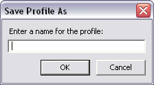
Enter a name for your new profile. Note that you cannot save over the existing "Default" profile. Also, if you enter a profile name that is already in use, VRC will overwrite the existing profile.
Now that you have saved your profile with a new name, any changes you make will be saved under this new profile.
Deleting a Profile
If you wish to delete an existing profile, simply select it within the Profile Selection Window and press the Delete key. You will be prompted to confirm that you actually want to delete the selected profile.
Note that you cannot delete the "Default" profile.
Saving a Profile
While you are working with VRC, any time you make changes to your configuration, you may want to update your currently loaded profile with these changes. To do so, simply choose "Save Profile" from the "File" menu. Your VRC.ini file will be updated with the new profile configuration, and a confirmation message will be shown in the Primary Display.
Note that if you attempt to overwrite the "Default" profile, you will be prompted to enter a new name for the profile instead.
Importing Profiles
VRC provides a way for you to import settings from another controller's VRC.ini file. This function is especially useful to allow instructors to share pre-made profiles for their region.
To import one or more profiles, select "Import Profiles..." from the "Tools" menu on the Profile Selection Window. You will be prompted to locate and select an .ini file on your hard drive. Once you select a file, you will see a new window similar to the following:
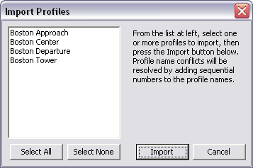
All profiles found in the selected file (with the exception of the Default profile) will be shown in the list on the left side of the window. Using your mouse, select one or more profiles to import, then press the Import button. The selected profiles will be added to your main VRC.ini file and will appear in your Profile Selection Window. If you try to import a profile which has a name matching one of the profiles already in your VRC.ini file, then the newly-imported profile will have a number appended to its name, such as "Boston Center (2)".
Merging Profiles
VRC also provides a way for you to copy groups of settings from one profile to another. This is useful if for example you have changed the color settings in one profile, and you wish to use the same color settings in another profile. This is also handy for importing regional defaults (such as radio frequencies and voice channels) from a file provided by your local instructors.
To merge selected settings between two profiles, select "Merge Profiles" from the "Tools" menu on the Profile Selection Window. A new sub-menu will appear with two choices: "Merge From File..." and "Merge Existing...". Choose "Merge From File..." if you wish to merge groups of settings from a profile found in an INI file you received from someone else. Choose "Merge Existing..." if you wish to merge groups of settings from one of your own profiles to another. If you choose to merge settings from a file, you will be prompted to locate and select an .ini file on your hard drive. Once you select a file, or choose to merge two of your existing profiles, you will see a new window similar to the following:
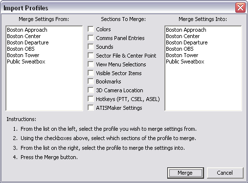
First, using the list on the left, select the profile you wish to merge settings from. This list will show all of the profiles found in the file you selected to merge from, or all of your existing profiles. Then choose which groups of settings you wish to merge into your profile. Then, using the list on the right, select which profile you wish to merge the settings into. This list will show all of the profiles in your main VRC.ini file.
Once you have made your selections, press the Merge button. All the selected groups of settings will be copied from the profile selected from the list on the left, and saved into the profile selected from the list on the right. Obviously, any merged settings will overwrite their previous values. There is no "undo" function, so make sure your selections are correct before pressing Merge!
Exporting Profiles
VRC also provides a way for you to export one or more profiles to an external file suitable for sharing with other controllers. This is useful if you wish to create a set of standard pre-configured profiles for other controllers working in your area.
To export one or more profiles, select "Export Profiles..." from the "Tools" menu on the Profile Selection Window. You will see a new window similar to the following:
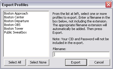
Using your mouse, select one or more profiles to export. Then enter a filename for the export in the box provided. Enter only the filename, and not the extension. VRC will automatically add the .ini extension to the file. Then press the Export button. VRC will create the specified file and copy the selected profiles into the file. Your CID and Password will automatically be left blank in the exported profiles. You can then send this file to other controllers, and they can then import the profiles or merge selected settings from them.
Color Profiles
Introduction
Starting with version 1.2, VRC allows you to define multiple color profiles. A color profile is a set of color selections which you can apply to any scope window. Each scope in a given session profile can have a different color profile assigned to it. This allows you to have one scope set up in one radar mode with colors appropriate to that mode, and another scope using a different radar mode with a different set of colors. For example, a tower controller might have one scope window set up using an ASDE-style ground radar color profile, with another scope set up using a DBRITE-style color profile.
The first time you run VRC, there will be a few color profiles available, including a default color profile, and a few profiles specifically made for certain radar modes such as TAAATS, Park Air, and STARS.
If you upgrade from a version of VRC prior to version 1.2, color profiles will be created based on the colors you have selected for each of the session profiles in your INI file. These color profiles will be named "Imported 1", "Imported 2", etc. You may want to rename them to something more intuitive.
To modify your color profiles, choose "Color Profiles..." from the "Settings" menu. You will see the following window:
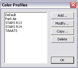
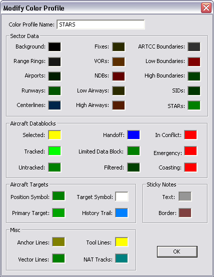
Double-click on the color profile you wish to modify, or select it from the list and press the "Modify..." button. You will see the color profile editing window:
Refer to Configuring the Scope for more information about modifying scope colors.
Creating a New Color Profile
To create a new color profile, click the "Add..." button on the Color Profiles window shown above. A new color profile will be created with a default name, and you will see the color profile editing window. You can make changes to any of the colors and give the color profile a new name. Press the "OK" button to save your changes.
Deleting a Color Profile
To delete a color profile, select it from the list and press the "Delete" button. You will be prompted to confirm that you actually wish to delete the color profile. Once you delete it, any scopes in your session profiles that used the deleted color profile will be set to use the default color profile.
Importing/Exporting Color Profiles
You can import and export color profiles in the same manner as you import or export regular session profiles. Refer to the documentation on session profiles for more information.
Configuring VRC (General Settings)
Most of the VRC configuration settings can be found in the General Settings window. You access this window by selecting "General..." from the "Settings" menu on the Primary Display. Starting with version 1.2, the General Settings window consists of a collection of tabbed pages, each of which contain a group of related configuration options. Each tab is described below:
Miscellaneous Tab
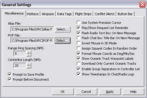
- Alias File
- Press the "Select..." button to the right of the text box in order to select your alias file. Alias files define command shortcuts which you will enter in the command line when working with pilots via text. Consult the training staff for the area where you will be controlling in order to obtain the appropriate alias file.
- POF File
- Press the "Select..." button to the right of the text box in order to select your POF file. A POF file defines all the ATC sectors in and around the area where you are controlling. The information in the file defines, among other things, the tag shown in ARTS mode, the two-character ID shown in the controller list for each controller, and the various sector "Radio Names". Consult the training staff for the area where you will be controlling in order to obtain the appropriate POF file.
- Range Ring Spacing
- This sets the distance in nautical miles between the range rings drawn on the scope. See "Configuring the Scope" for details on activating the range rings.
- Centerline Length
- This sets the length in nautical miles of runway centerlines drawn on the scope. See "Configuring the Scope" for details on activating the centerlines.
- Prompt to Save Profile
- If this option is checked, you will be prompted before exiting VRC or loading a new profile if you have made changes to the current profile without saving them.
- Prompt Before Disconnect
- If this option is checked, you will be prompted before exiting VRC, loading a new profile, or disconnecting from the network if you are currently connected.
- Use System Precision Cursor
- If this option is checked, the "Precision Select" cursor defined in your Windows Mouse control panel will be used instead of the DSR-style cursor (or the ARTS cursor) included with VRC.
- Play/Show Request List Reminder
- If this option is checked, and you have aircraft in your reminder list, every 30 seconds a sound will be played and a message will be shown listing the aircraft that are in your reminder list. The aircraft are also shown in red in your Aircraft List. See "Some Useful Tools" for details on the reminder list.
- Flash Radio Text Box On New Message
- If this option is checked, the radio history box on your Primary Display will flash when new text messages are received from pilots on your primary frequency or on the guard frequency. Click on the radio history area or press CTRL-SPACE to stop the flashing.
- Flash Chat Box Title Bar On New Message
- If this option is checked, the title bar will flash in a chat window when a new message is received for that window. The flashing will stop when you click on the chat window.
- Invert Mouse in 3D Mode
- If this option is checked, the pitch up/down movement sensing for your mouse will be reversed in the 3D radar mode.
- Assign Squawwk Codes In Random Order
- If this option is checked, squawk codes will be assigned to aircraft from your range at random. This can help prevent duplicate squawk code assignments among controllers sharing the same code range.
- Format Mouse Coords as Deg/Min/Sec
- If this option is checked, and you have enabled the display of the mouse location on the View menu, the mouse coordinates will be shown in degrees, minutes, and seconds instead of of in decimal degrees.
- Show Oceanic Track Waypoint Labels
- If this option is checked, labels for each waypoint on an oceanic track will be displayed along with the track route itself.
- Download Only Curernt Oceanic Tracks
- If this option is checked, only those oceanic tracks that are active for the current day will be shown in the Oceanic Tracks window. Otherwise, all recent tracks including those from previous days will be shown.
- Enable Group SEparators in Controller List
- If this option is checked, a separator line will be shown for each grouping of controllers (based on facility type, etc.) in the Controller List.
- Show Timestamps In Chat/Radio Logs
- If this option is checked, a timestamp will be shown for each receieved radio or chat message.
Hotkeys Tab
- Aircraft Select Key
- To set a new Aircraft Select (ASEL) key, click in the box and press the key. The key name will be shown in the box. For details on when the ASEL key is used, see "Selecting Aircraft".
- Controller Select Key
- To set a new Controller Select (CSEL) key, click in the box and press the key. The key name will be shown in the box. For details on when the CSEL key is used, see "Chat Windows".
- Push to Talk Key
- To set a new Push to Talk (PTT) key, click in the box and press the key. The key name will be shown in the box. The PTT key is used for voice transmissions either to pilots or on the land line with other controllers. Select a key which will not be used for any other reason while working in VRC. The left or right CTRL key are good choices.
Airspace Tab
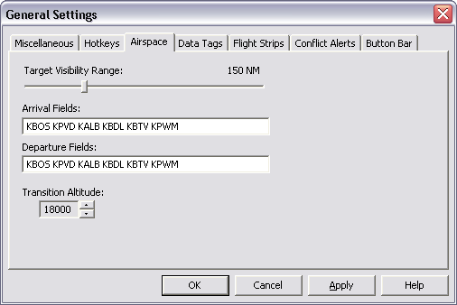
- Target Visibility Range
- This slider sets the range at which you will see targets on your scopes. This value is given in nautical miles from your "visibility center(s)". (See "Configuring the Scope" for details on setting your visibility center(s).) It is important that you keep this slider set as low as possible. The higher your visibility range, the more bandwidth you consume on the network. It should be set to only cover your airspace. If you are working Ground or Clearance Delivery, it should only cover the airport surface area, which would generally mean the minimum setting of 5 miles.
- Arrival and Departure Fields
- These lists determine which aircraft appear on your Aircraft List. These are simple comma or space-separated lists of ICAO codes.
- Transition Altitude
- This setting defines the altitude (in feet) at which VRC will begin to format altitudes in terms of flight levels instead of feet. This also affects the display of altitudes (true versus pressure altitude) in data blocks for aircraft above this transition level. If you are unsure what the transition level is for the area where you intend to control, consult your training staff.
Data Tags Tab
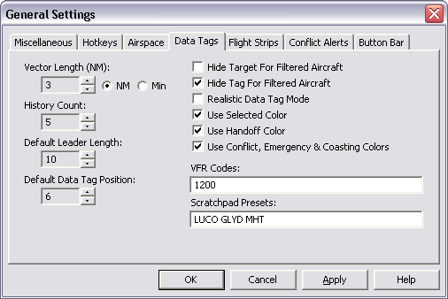
- Vector Length
- In the DSR radar mode, when tracking an aircraft, a vector line will be drawn from the aircraft primary target in the direction of the aircraft's travel. This setting determines the length of the vector line. It is either specified in nautical miles or in minutes, depending on which of the two radio buttons (just below the text box) is selected.
- History Count
- In all radar modes, a history trail for moving aircraft will be drawn. This setting determines how many such history targets are drawn. Set this to zero to disable target histories.
- Leader Length
- This specifies the default length (in pixels) of the leader line drawn between a target and its data block. Note that you can use the mouse to click and drag a data block to a new position, with a different leader length if desired.
- Default Tag Position
- This specifies the default position of a data block for new aircraft. The value corresponds to the position of the number on your numeric keypad. Note that you can reposition data tags by dragging them with the mouse.
- Hide Target For Filtered Aircraft
- If this option is checked, any aircraft outside of your defined airspace (see below) will not have a target symbol drawn.
- Hide Tag For Filtered Aircraft
- If this option is checked, any aircraft outside of your defined airspace (see below) will not have a data tag drawn.
- Realistic Data Tag Mode
- If this option is checked, the Realistic Data Tags mode is enabled. See the Advanced Topics section for more information.
- Use Selected Color
- If this option is checked, the currently radio-selected aircraft target will be drawn in the "Selected" color from the current Color Profile. Otherwise, the target will be drawn using the normal color for unselected aircraft. This option is provided for the purposes of realism.
- Use Handoff Color
- If this option is checked, the target for any aircraft you are handing off to another controller, or for any aircraft being handed off to you will be drawn in the "Handoff" color from the current Color Profile. Otherwise, the target will be drawn using the normal color. This option is provided for the purposes of realism.
- Use Conflict, Emregency & Coasting Colors
- If this option is checked, targets that are currently in any of the listed conditions will use the appropriate color from the current Color Profile. Otherwise the target will be drawn using the normal color. This option is provided for the purposes of realism.
- VFR Codes
- You can specify a set of codes (comma-separated) or even ranges of codes here. Any aircraft squawking a code included in this set will be drawn as a VFR target. Example values: "1200", "1200,1201,1202", "1200-1277,1300-1355,1234".
- Scratchpad Presets
- You can specify a list of preset scratchpad codes here. Separate them with spaces. This list will appear when you right-click a target and choose "Set Scratchpad" from the pop-up menu.
Flight Strips Tab
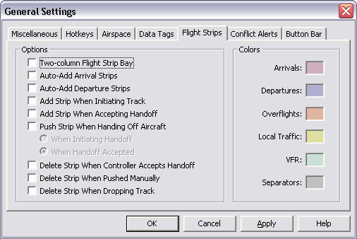
- Two-column Flight Strip Bay
- If this option is checked, the Flight Strip Bay will contain two columns for strips. If this option is unchecked, the Flight Strip Bay will consist of only one column. See "The Flight Strip Bay" to learn how to use the Strip Bay.
- Auto-Add Arrival Strips
- If this option is checked, whenever a flight plan is received for an aircraft which is arriving at a field on your arrival airport list, a flight strip for the aircraft will automatically be added to your Flight Strip Bay. See "The Flight Strip Bay" to learn how to use the Strip Bay.
- Auto-Add Departure Strips
- If this option is checked, whenever a flight plan is received for an aircraft which is departing from a field on your departure airport list, a flight strip for the aircraft will automatically be added to your Flight Strip Bay. See "The Flight Strip Bay" to learn how to use the Strip Bay.
- Add Strip When Initiating Track
- If this option is checked, a flight strip will be added to your Flight Strip Bay whenever you initiate track on an aircraft.
- Add Strip When Accepting Handoff
- If this option is checked, a flight strip will be added to your Flight Strip Bay whenever you accept a handoff of an aircraft.
- Push Strip When Handing Off Aircraft
- If this option is checked, whenever you handoff an aircraft to another controller, you will automatically push a flight strip to the receiving controller. This action can happen either when you initiate the handoff, or when the receiving controller accepts the handoff, depending on the radio button setting here.
- Delete Strip When Controller Accepts Handoff
- If this option is checked, and you handoff an aircraft to another controller, if you have a flight strip for the aircraft you handed off, it will be deleted.
- Delete Strip When Pushed Manually
- If this option is checked, and you push a flight strip to another controller, that strip will be deleted from your Flight Strip Bay.
- Delete Strip When Dropping Track
- If this option is checked, and you drop track on an aircraft, if you have a flight strip for the aircraft, it will be deleted.
- Strip Color Options
- The six color options shown here allow you to determine the background color of various types of flight strips in your Flight Strip Bay.
Conlict Alerts Tab
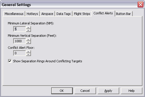
- Minimum Lateral Separation
- This sets the minimum required lateral separation in nautical miles between aircraft before a conflict alert is sounded. Use the buttons to the right of the text box to increase or decrease the value.
- Minimum Vertical Separation
- This sets the minimum required vertical separation in feet between aircraft before a conflict alert is sounded.
- Conflict Alert Floor
- Below this level, no conflicts will be detected. This value is specified in feet.
- Show Separation Rings Around Conflicting Targets
- If this option is checked, a flashing red ring will be drawn around aircraft in conflict. The radius of this ring will be equal to the lateral minimum value set above.
See "Conflict Alerts" for details on how conflict alerts are detected and displayed.
Button Bar Section
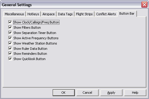
Each checkbox here simply causes the associated button type to be shown or hidden, allowing you to customize which types of buttons appear in the Button Bar on your Primary Display.
Once you have made any changes to the setting in the General Settings window, press the "Apply" button to activate the changes. The General Settings window will remain open, allowing you to make further changes if necessary. If you wish to save your changes and close the General Settings window, press the "OK" button. If you wish to cancel your changes and stay with the previous settings, press the "Cancel" button.
Important: changes to items in the General Settings window will not be saved in your session profile until you choose "Save Session Profile" from the "File" menu. Until then, they will only take effect during the current VRC session. This applies to all other configuration items as well.
Configuring Sounds
Many different "events" within VRC can have sounds associated with them. In order to select an event and associate a sound with it, first open the Sounds Window by choosing "Sounds..." from the "Settings" menu on the Primary Display. The following window will be shown:
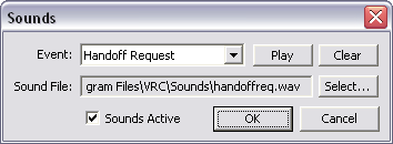
First, using the "Event:" dropdown, choose the event with which you want to associate a sound. Any existing sound will be shown in the "Sound File:" box. To change the associated sound, press the "Select..." button. This will show a standard file window with which you can locate and select the sound file you wish to use for the selected event. All sounds must be standard Windows .wav files. The sounds can be anywhere on your hard drive. They do not have to be in the default folder.
To hear the sound you have selected, press the "Play" button.
To clear the sound selection, press the "Clear" button. This will obviously mean that no sound will be played when the selected event occurs.
If you want to disable all sounds while still retaining your sound selections, uncheck the checkbox labelled "Sounds Active" at the bottom left corner of the window.
Once you are satisfied with your sound selections, press the "OK" button to save your changes. If you would like to cancel your changes and retain the previous selections, press the "Cancel" button.
As with all other configuration items, changes to your sound selections will not be saved in your profile until you choose "Save Profile" from the "File" menu. Until then, they will only take effect during the current VRC session.
Configuring Audio Devices
For the purposes of air-to-ground or ground-to-ground voice communications, VRC can make use of any audio hardware available in your system. In order to configure which audio devices are used, select "Audio Devices" from the "Settings" menu on the Primary Display. The following window will be shown:
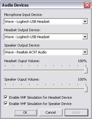
The "Microphone Input Device" is obviously used to record your voice for sending to pilots or other controllers.
The "Headset Output Device" is used when you have opened a voice channel (either air-to-ground or ground-to-ground) and assigned it to your headset.
The "Speaker Output Device" is used when you have opened a voice channel (either air-to-ground or ground-to-ground) and assigned it to your speakers.
See "The Comms Panel", "Communicating with Pilots", and "Ground-to-Ground Communications" for details on routing voice transmissions to your selected audio devices.
The "Headset Output Volume" and "Speaker Output Volume" sliders are used to set the volume of incoming voice transmissions sent to your headset or speakers, respectively.
The VHF Simulation checkboxes determine whether or not VRC applies a bandpass filter to the audio for your output devices. If enabled, most of the low-frequency sound will be removed from the audio. This can often make pilots much easier to understand when using speakers or headphones with a fair amount of bass response.
Once you are satisfied with your audio device configuration, press the "OK" button to save your changes. If you would like to cancel your changes and retain the previous settings, press the "Cancel" button. If you would like to save your changes without closing the Audio Devices window, press the "Apply" button.
As with all other configuration items, changes to your audio device configuration will not be saved in your profile until you choose "Save Profile" from the "File" menu. Until then, they will only take effect during the current VRC session.
Calibrating Your Microphone
In order to accurately transmit your voice over the network, VRC needs to test the sensitivity of your microphone and the level of background noise in your room. This is called "Calibrating" your microphone. This calibration only needs to be done once for any given microphone device. If you change to a different sound card or purchase a new microphone, you will need to perform this calibration again for each profile you intend to use with the new device.
To begin the microphone calibration, choose "Calibrate Mic..." from the "Settings" menu on your Primary Display. The following confirmation window will be shown:
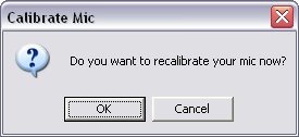
Press the "OK" button to continue. Press the "Cancel" button if you change your mind and do not want to recalibrate your microphone at this time.
If you press the "OK" button, the following window will be shown:
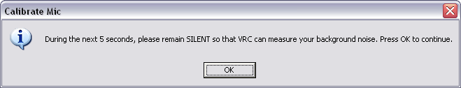
Press the "OK" button and remain silent until the next window appears. This will take about 5 seconds. During this time, VRC is measuring the level of background noise in your room. VRC will use this measured level to determine the "noise floor" for your room. Any sounds at or below this noise floor will not be sent while you are transmitting on voice. For this reason, it is important to avoid loud noises during this 5 second period.
After about 5 seconds, the following window will be shown:

Press the "OK" button and begin speaking in a normal voice as though you were talking to pilots. Speak at the same volume you will use while controlling. During the next 5 seconds or so, VRC will be recording your voice and measuring its volume level. This is done to make sure the volume of your voice is sufficiently loud enough to overcome the previously measured noise level in your room.
After the 5 second recording period, a window will be displayed showing the results of your microphone calibration. If the calibration succeeded, and your microphone is set properly, then the window will look similar to the one shown here:
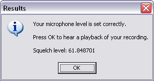
If the window contains a message informing you of a problem with your microphone levels, then you may need to correct the problem either by lowering the ambient noise level in your room, or by increasing your microphone recording volume in your Windows mixer settings. Note that some sound drivers include a "boost" option for the microphone input level, which may be needed if VRC tells you that your microphone is too quiet.
After pressing the "OK" button, your voice recording will be played back so that you can confirm that it was recorded properly. At the end of this playback, you will see the following confirmation message:
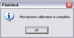
Press the "OK" button. Your microphone calibration is complete and you should now save your profile. See "The Profile System" for details.
Configuring the Scope
This section describes some of the common functions you can use to control the way your scope looks and how the sector file data is drawn.
Zooming & Panning the Scope
To zoom the scope, use the mousewheel or the F11/F12 keys. Panning the scope can be accomplished by holding down the right mouse button and moving the mouse. You can also instantly recenter the scope by double-right-clicking on a point.
The View Menu
The View Menu is used to toggle the display of various items on the scope. Here's a screenshot:
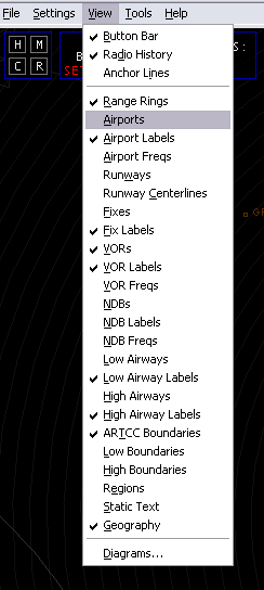
The "Button Bar" option toggles the display of the Button Bar, which is the row of buttons across the very top of the Primary Display.
The "Radio History" option toggles the display of the radio history area at the bottom of the Primary Display.
The "Anchor Lines" option toggles the display of anchor lines on the scope. Refer to the Anchors section of the "Some Useful Tools" page for details on creating anchors.
The next section of the View Menu contains toggles for all the various types of data contained in the sector file, as well as an option to toggle the range rings on and off.
The last item in the View Menu, labelled "Diagrams...", opens a new window which lists all the items from the SIDS and STARS sections of your currently-loaded sector file. Refer to the following section for details.
The Diagrams Window
The Diagrams Window is accessed by choosing "Diagrams..." from the "View" menu or by pressing CTRL+G. Here's a screenshot:
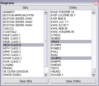
The two lists in this window include the entries from the SIDS and STARS sections of the currently-loaded sector file. (Note that those sections are often used for other types of diagrams such as airspace diagrams, sector split definitions, etc.) To enable or disable the display of any of the listed diagrams, simply click on the entry. Any entries currently being drawn are highlighted in gray. Press the buttons underneath each list to unselect all entries in the associated list.
When you are done making selections from the Diagrams lists, press the Esc key or press the X icon in the upper-right corner to close the window.
Note that each open display has its own Diagrams Window. Selected diagrams are only visible in the associated Display.
Setting Sector Data Colors
All color selections in VRC are made via the color profiles. You can modify the colors in a color profile by choosing "Color Profile->Modify Current..." from the "Settings" menu. Here's a screenshot:
In order to change one of the color settings, simply click on the colored box next to the item you want to change. A standard color selection window will appear. Choose your color and press "OK". The new color will be shown in the box next to the item name. Note that new color assignments take effect immediately, though you obviously won't see the color change unless the color profile is in use on at least one of your scope windows. Changes to color profiles are saved in the INI file once you choose "Save Profile" from the "File" menu.
Most of the color items in this window are self-explanatory, but two of them warrant an explanation. The first is "Anchor Lines". The color you select here will be used when you set an "Anchor" for an aircraft and you have "Anchor Lines" enabled in the "View" menu. See "Some Useful Tools" for more information on Anchors.
The other item that may not be self-explanatory is "Tool Lines". This color is used for several different functions within VRC that draw lines on the scope. They include the "Ruler Line", the "Separation Predictor Lines", and the "Route Line". See "Some Useful Tools" for more information on these functions. The Tool Line color is also used when highlighting a fix using the .find command or when showing your visibility center(s).
Scope Configuration Commands
Following are some of the more important and most commonly-used commands for working with the scope:
- .rings POINT
- Centers the range rings on the specified POINT. (VOR, Airport, Intersection, etc.)
- .norings
- Disables range rings
- .center POINT
- Centers the scope on the specified POINT.
- .vis POINT
- Sets your primary visibility center at the specified POINT.
- .vis2/.vis3/.vis4 POINT
- Sets one of your secondary visibility centers at the specified POINT.
- .novis
- Clears all visibility centers. The center point of the scope will then be your visibility center.
- .showvis
- Shows a circle around any configured visibility centers.
- .ff FIX ...
- Toggles the display of one or more individual intersections.
- .fv VOR ...
- Toggles the display of one or more individual VORs.
- .fn NDB ...
- Toggles the display of one or more individual NDBs.
- .fa AIRPORT ...
- Toggles the display of one or more individual Airports.
- .fc RUNWAY ...
- Toggles the display of one or more individual runway centerlines.
- .fw AIRWAY ...
- Toggles the display of one or more individual airways.
- .fd Diagram Name|Diagram Name|Diagram Name|...
- Toggles the display of one or more diagrams (SIDs/STARs).
- .nofixes
- Disables the display of fixes toggled on via the .ff command.
- .novors
- Disables the display of VORs toggled on via the .fv command.
- .nondbs
- Disables the display of NDBs toggled on via the .fn command.
- .noairports
- Disables the display of airports toggled on via the .fa command.
- .nocenterlines
- Disables the display of runway centerlines toggled on via the .fc command.
- .noairways
- Disables the display of airways toggled on via the .fw command.
- .nodiagrams
- Disables the display of all diagrams toggled on via the .fd command.
Visibility Center(s)
As mentioned above, you can use the .vis/.vis2/.vis3/.vis4 commands to define the "Visibility Center(s)" for your scopes. A visibility center determines the center point of your sector. Combined with your visibility range, the visibility center is used by the network to determine which aircraft are visibile on your scope. For example, if you issue the following command:
.vis KBOS
Then your primary visibility center will be set at the Boston airport. If your visibility range is set to 100 NM, then you will be able to see targets within 100 NM of KBOS, regardless of where your scope is actually centered. If your scope was centered on the Syracuse VOR (SYR) which is about 250 miles west of KBOS, you would still only see aircraft around KBOS ... you would not see aircraft near SYR.
In some cases, a single center point isn't enough to cover a very large or oddly-shaped sector. If this applies to your sector (generally this only happens in Oceanic sectors) then you can define additional (secondary) visibility centers. You can specify 3 secondary visibility centers, for a total of four. Your visibility range applies separately to each visibility center. For example, in addition to the .vis command issued in the example above, if you entered:
.vis2 SYR
Then you would still see aircraft within 100 NM of KBOS, but you would also see aircraft within 100 NM of the Syracuse VOR. The secondary visibility centers allow you to expand the range of your radar in order to cover extremely large or strangely-shaped sectors. Please use them with caution, and only when absolutely necessary, since each time you define an additional visibility center, you consume additional network bandwidth. For example, a controller with three visibility centers defined consumes three times as much bandwidth as a controller with just the primary visibility defined, assuming they both have the same visibility range.
Note that your visibility center(s) also determine which other controllers you will see in your Controller List.
You can change (update) a visibility center at any time simply by re-issuing the command with a new point. If you wish to clear your visibility centers and revert to having only one, issue the .novis command. If you have no visbility centers defined, then the center of your scope becomes the visibility center. This of course means that your visibility center moves as you pan the scope. This is why it's always a good idea to set your primary visibility center (using .vis) as soon as you open a profile and/or load a new sector file. (Loading a new sector file clears any defined visibility centers.)
Airspace Filters
In VRC, your airspace filters are defined simply by a floor and a ceiling. If you define this floor and/or ceiling, and your airspace filters are active, then targets above your ceiling or below your floor will be shown using the "Filtered" color. Some controllers like to set the filtered color to something quite dark, so that the targets can be seen, but they are not distracting and so that they are not easily mistaken for aircraft within the defined airspace.
You also have the option of hiding the data block and/or target symbol for filtered aircraft. (See "Configuring VRC.")
Starting with VRC 1.2, you can define airspace filters separately for each scope. To set the filters, press Ctrl-Alt-F and set the appropriate values in the resulting popup window. You can also choose "Filters->Configure..." from the "Settings" menu.
You can also define a hard radar floor for each scope. The radar floor is different from the airspace floor in that aircraft below the radar floor will never be displayed, regardless of your filter settings. This is to allow you to simulate line-of-sight radar coverage in hilly or mountainous areas.
To enable or disable the airspace filters, press Ctrl-F, or choose "Filters->Enable..." from the "Settings" menu. On the primary scope, you can also click the Filters button in the button bar to toggle the filters on and off for the primary scope. Note that the radar floor setting is always in effect, whether your airspace floor and ceiling are enabled or not.
The Button Bar
As mentioned above, you can turn the Button Bar on and off using the "View" menu. You can also select individual types of buttons using the "General..." option in the "Settings" menu. For example, if you are working Ground, you might not have any need for the Timer button, which is normally used for wake turbulence separation by Tower. In that case, you might disable the Timer button using the checkbox in the General Settings.
Saving Your Configurations
Remember to always save your configurations in a profile for easy recall the next time you work the same position!
The Weather Panel
VRC's Weather Panel is one of several "Tool Windows" available to you during a controlling session. The Weather Panel lists all of the weather stations that you are currently monitoring, along with the latest altimeter and winds reported for each station. VRC checks for new METARs for each station every 5 minutes. The lower half of the Weather Panel is used to display full METARs for selected stations, or to show METARs retrieved as a result of the .WX command.
To open the Weather Panel, choose "Weather Panel" from the "Tools" menu. The following is an example of the Weather Panel with five stations currently being monitored:
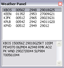
In order to view the full METAR for any of the listed stations, simply click on it with the left mouse button.
To view a pop-up menu with options for the selected station, right-click on any station in the list.
To add stations to the list, or to remove stations from the list, press the F2 key. This will place the .QD command in the command line. Complete the command by entering a list of weather stations to add to or remove from the list. Example:
.QD KBOS KALB
This would remove KBOS from the list shown in the example screenshot (since it is already in the list) and add KALB.
You can also press the F2 key followed by slewing a target or pressing the ASEL key if an aircraft is already selected. This will add the selected aircraft's destination field to the list of stations in the weather panel.
To see the METAR for a station without adding it to the list of monitored stations, press the F7 key. This will place the .WX command in the command line. Complete the command by entering the ICAO code for the airport, such as .WX KIAD. VRC will then fetch the METAR for KIAD and display it in the lower half of the Weather Panel. This will also cause the Weather Panel to be shown if it is currently hidden.
You can change the height of the Weather Panel using your mouse in the same way you resize normal windows. You can hide the Weather Panel by pressing the X icon in the upper-right corner of the window, or by pressing the Esc key.
Similar to the other Tool Windows in VRC, you can "roll up" the Weather Panel by double-clicking in the title bar. Double-click the title bar again to "unroll" the window.
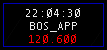
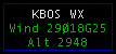
Weather Buttons
The list of stations in the Weather Panel also determines which weather buttons will be shown in the Button Bar. For each station, a weather button will be shown (if enabled in your settings) which looks similar to this example:
You can view the full METAR for any monitored weather station by clicking on the associated weather button. The full METAR will be shown just below the button bar, as in this screenshot:
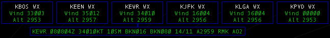
Click the weather button again to hide the full METAR.
The Controller List
VRC's Controller List is one of several "Tool Windows" available to you during a controlling session. It is also known as the "CL". To open the CL, choose "Controller List" from the "Tools" menu. Here's a screenshot:
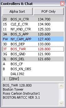
The Controller List is primarily used to display other controllers within your range. It is also used to display chat groups or private chats you have open with pilots or controllers not within your range.
Controllers within your range are shown with a two-character "Sector ID" along with their callsign and primary frequency. They are normally sorted first by facility type then alphabetically by callsign. In order to sort all controllers alphabetically, ignoring their facility type, press the "Alpha Sort" button at the top of the window.
Observers are shown at the bottom of the list of controllers. They are shown with a single-character ID and their callsign.
If a pilot or out-of-range controller messages you, his/her callsign will also be included in the controller list. It will be shown as just the callsign, with no ID next to it.
Chat groups are shown below all other entries. The name of the chat group is contained within square brackets.
To open a chat window with any controller, observer or pilot in the list, simply double click their respective entry. A new chat window will be opened, or the keyboard focus will be switched to the existing chat window if there is one. This applies to existing chat groups as well.
To view a pop-up menu with options for the selected controller, right-click on any entry in the list.
If an entry in the CL is highlighted in blue, that means that you have at least one chat message waiting from that person. If an entry is highlighted in gray, that means that person is a member of the currently selected chat group. If an entry is highlighted in red, that means you have a pending incoming or outgoing intercom call with that person.
If the text of an entry is blue, that means that person is monitoring you. They can hear everything that you hear or transmit on voice. If the text of an entry is green, that means you are on an intercom call with that person. If the text of an entry is dark green, that means you are on an intercom call with that person, but the call is currently on hold. If the text of an entry is orange, that means that person has requested help. (See "Some Useful Tools") If the text of an entry is red, that means that person is overriding you. (See "Ground-to-Ground Communications") If the text of an entry is pink, that means that person is requesting relief. (See "Some Useful Tools")
If you wish to filter out observers, you can press the "POF Only" button at the top of the window. This will mean that only controllers who have a matching entry in your POF file will be shown in the list. Any controller or pilot for whom you have a waiting chat message will also be shown even if the "POF Only" button is depressed.
You can open a chat box (or switch to an existing chat box) with any controller, observer or chat group by entering the one- or two-character ID into the command line on the Primary Display and pressing your CSEL key. See "Chat Windows" for details.
Clicking on an in-range controller or observer brings up some information about that person in the box at the bottom of the CL. This information includes:
- Callsign
- Primary frequency
- Radio name (if defined in your POF file)
- Full name
- Rating
- Sector file name
- Help request message (if any)
You can change the height of the Controller List using your mouse in the same way you resize normal windows. You can hide the Controller List by pressing the X icon in the upper-right corner of the window, or by pressing the Esc key. You can also "roll up" the window by double-clicking in the title bar. Double-click the title bar again to "unroll" the window.
The Aircraft List
VRC's Aircraft List is one of several "Tool Windows" available to you during a controlling session. It is also known as the "Arrival/Departure List". To open the Aircraft List, choose "Aircraft List" from the "Tools" menu. Here's a screenshot:
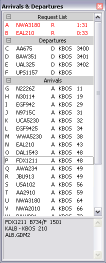
VRC adds aircraft to this list for any one of three reasons:
- The aircraft is departing from a field included in your Departure Fields list. (See "Configuring VRC")
- The aircraft is arriving at a field included in your Arrival Fields list. (See "Configuring VRC")
- The aircraft is on your reminder list. (See "Some Useful Tools")
Aircraft on your reminder list are shown first. They are displayed in red text along with the letter "R" and a timer showing how long the aircraft has been on your reminder list.
Departures are shown next. They are shown in black text along with the letter "D", the ICAO code for the field they are departing from, and their assigned squawk code, if any. Departures are sorted by callsign. Once the aircraft is airborne (determined by a ground speed above 50 knots) it no longer appears as a departure on this list.
Arrivals are shown next. They are shown in black text along with the letter "A", the ICAO code for the field they are arriving at, and their current distance from that field. Arrivals are sorted by distance from their arrival field.
You can click on any entry in the list to see details about the aircraft in the box at the bottom of the Aircraft List. These details include:
- Callsign
- Aircraft type
- Transponder code assigned to the aircraft
- Transponder code the aircraft is currently squawking if different from the assigned code
- Departure field
- Arrival field
- Route
You can right-click any entry to get a pop-up menu containing many different functions which you can perform on the selected aircraft.
You can double-click any entry in the list in order to load that aircraft's flight plan into the Flight Plan Editor window. See "Viewing & Editing Flight Plans" for details.
If you hold the Alt key and click an entry in the list, a flight strip for that aircraft will be added to the Flight Strip Bay. See "The Flight Strip Bay" for details.
Note that you can use the single-character indices in this list for selecting aircraft on the command line. See "Selecting Aircraft" for details.
You can change the height of the Aircraft List using your mouse in the same way you resize normal windows. You can hide the Aircraft List by pressing the X icon in the upper-right corner of the window, or by pressing the Esc key. You can also "roll up" the window by double-clicking in the title bar. Double-click the title bar again to "unroll" the window.
Finally, you can double-click one of the separators, or single-click the +/- icon in the separator to show or hide that group.
The Comms Panel
VRC's Communications Panel is one of several "Tool Windows" available to you during a controlling session. To open the Comms Panel, choose "Comms Panel" from the "Tools" menu, or click on the button in your Button Bar which shows the clock, your callsign and your primary frequency. Here's a screenshot of the Comms Panel:
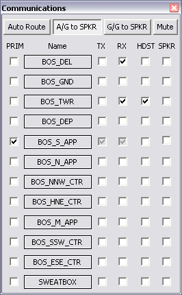
Each horizontal row of checkboxes (and its associated button) is called an "entry." Each of the twelve entries represents a single frequency which you can tune in on text, voice, or both. Each entry has the following four items associated with it:
- Short descriptive name
- Numeric radio frequency
- Voice server hostname
- Voice channel name
The first two items are required, and the last two (the voice-related items) are optional. The short descriptive name is what appears on the entry's button. It has no purpose other than to identify the frequency for your own reference when selecting frequencies to use during your VRC session.
Each entry also has five checkboxes associated with it:
- PRIM
- The first checkbox (to the left of the button) is used to set the entry's frequency as your primary frequency. This is the frequency that pilots will contact you on. You can only have one primary frequency set at a time, so only one entry can have its primary frequency checkbox checked. Once you check the PRIM checkbox for one entry, the PRIM checkbox is automatically unchecked for all other entries. Also, if you check the PRIM box, the TX and RX boxes (see below) will automatically be checked. This is because you obviously must be set to transmit and receive on your primary frequency.
- TX
- The second checkbox (to the right of the button) is used to enable transmitting on the frequency. If this checkbox is checked, whenever you send text radio messages, they will go out on this frequency as well as any other frequencies for which you check the TX box. Also, if you have a voice channel configured in this entry (see below), and you have either the HDST or SPKR checkbox checked (see below), then whenever you press your Push-To-Talk (PTT) key, your voice will be transmitted to the voice channel associated with this entry. Note that checking the TX box will automatically check the RX box as well if it is not already checked. This is because you cannot transmit on any frequency without also receiving it, since that wouldn't make much sense.
- RX
- The third checkbox is used to enable receiving on the frequency. If this checkbox is checked, any text messages sent by pilots or controllers on this frequency will be shown in your radio history area. Also, if you have a voice channel configured for this entry (see below), and you have either the HDST or SPKR checkbox checked (see below), you will hear any incoming voice transmissions from pilots or controllers using that voice channel.
- HDST
- The fourth checkbox is used to connect to the voice channel associated with this entry, and route the audio to the sound device you have configured for your headset. When you first check the box, it will be disabled (greyed out) for a brief moment while VRC connects to the voice server. Once the voice connection is made, the checkbox will be enabled again. Note that if you check the HDST box, the RX box will automatically be checked if it isn't already. Also, the SPKR box will be unchecked, since you cannot route voice to both your headset and speakers at the same time.
- SPKR
- The fifth and last checkbox is used to connect to the voice channel associated with this entry, and route the audio to the sound device you have configured for your speakers. When you first check the box, it will be disabled (greyed out) for a brief moment while VRC connects to the voice server. Once the voice connection is made, the checkbox will be enabled again. Note that if you check the SPKR box, the RX box will automatically be checked if it isn't already. Also, the HDST box will be unchecked, since you cannot route voice to both your headset and speakers at the same time.
Editing Entries
In order to edit the name, frequency, and voice channel information for an entry, simply click the entry's button. The Comms Panel will be expanded to show four edit fields and three buttons, as shown in this screenshot:
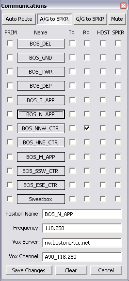
If you attempt to edit the information for a frequency that is currently in use, the edit fields will be disabled.
Enter any changes in the fields as indicated. The frequency for any position, as well as the voice server name and channel name, should be provided to you by the training staff at the area where you will be controlling. Note that the frequency must be entered as 3 digits followed by a decimal point, followed by three digits. Use extra trailing zeroes if necessary.
When you have finished making changes, press the "Save Changes" button. If you wish to cancel editing the entry and retain the previous settings, press the "Cancel" button. If you wish to remove an entry, press the "Clear" button followed by the "Save Changes" button.
After pressing the "Save Changes" or "Cancel" button, the Comms Panel window will be reduced in size to hide the edit fields. You can then make selections as normal, or close the panel by pressing Esc or by clicking the X icon in the upper right corner of the panel.
Routing Voice
The following functions are available for routing voice transmission. Use the three buttons across the top of the Comms Panel to enable/disable these functions:
- Auto Route
- If this button is depressed, all incoming air-to-ground voice transmissions will be routed to your speaker device while you are on a ground-to-ground (land line) call. See "Ground-to-Ground Communications" for details on using the land lines.
- A/G to SPKR
- If this button is depressed, all air-to-ground voice transmissions will be routed to your speaker device at all times, regardless of whether or not you are on a land line. This is useful when you normally use a headset and you need to step away from your computer for a moment but still want to hear pilot's transmissions.
- G/G to SPKR
- If this button is depressed, all ground-to-ground (land line) voice transmissions will be routed to your speaker device at all times.
- Mute
- If this button is depressed, your microphone will be muted. This is useful if for some reason you don't want your microphone to be active if another controller overrides you. Note that this also mutes your microphone for communications with pilots.
The SELCAL Panel
VRC's SELCAL Panel is one of several "Tool Windows" available to you during a controlling session. To open the SELCAL Panel, choose "SELCAL Panel" from the "Tools" menu. Here's a screenshot of the SELCAL Panel:
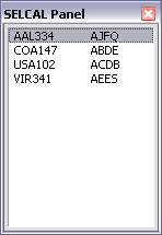
The SELCAL panel allows you to quickly see which aircraft within range have specified a SELCAL (SELective CALling) code in their flight plan remarks. SELCAL is a system used mainly by oceanic controllers to get a pilot's attention during long overseas flights when the pilot may have turned his com radio down due to the noise commonly found on long-range radio frequencies. When the controller sends a SELCAL signal, using the code assigned to the aircraft he wants to reach, it sounds a chime within the cockpit, alerting the pilots to turn up the com radio and respond.
When VRC detects that a pilot has specified his SELCAL code in his flight plan remarks, his callsign and code are added to the list in the SELCAL Panel. The controller can then simply double-click on the entry to send a SELCAL signal to the pilot.
Note that just because an aircraft is in the list, doesn't mean the pilot is actually tuned to your frequency, which means he won't necessarily hear the SELCAL tone in his cockpit.
The Incoming Chat Log
VRC's Incoming Chat Log is one of several "Tool Windows" available to you during a controlling session. To open the Chat Log, choose "Incoming Chat Log" from the "Tools" menu.
The Incoming Chat Log is used to display any chat messages you receive from other controllers or from pilots. You cannot respond to any chat messages using this window ... it is intended to be used to monitor incoming chat to decide whether or not you want to open a chat window with the sender and respond to the message. This is most useful for busy controllers that don't want to have to open a chat window every time a chat message comes in, but don't want to miss a potentially important message.
Setting your ATIS
On VATSIM, your "ATIS" is the text sent to pilots when they first tune your primary frequency. It is also known as your "Controller Info". Your ATIS can contain a variety of information, depending on your position, but at the very least, it should contain your name and your radio callsign, such as "Boston Center".
Depending on the position you are working, you may want to include some of the following items as well:
- Runway(s) in use at one or more fields
- Weather for one or more fields
- Current ATIS code
- Link to a controller feedback form
- Link to area charts
- Information about events or training in progress
- List of fields you are covering for coordination purposes
Basically, your ATIS should contain any information considered important for pilots flying under your control. Contact the training staff in the area where you will be controlling for specifics. Different areas have varying standards for what information should be contained in your ATIS.
Note that you do not need to include your voice channel URL (via the $mypvtrw or $myrw variables) anymore. VRC takes care of inserting that for you automatically, if you are using voice.
You set your ATIS using VRC's integrated ATISMaker function. If you have ever used the stand-alone version of ATISMaker, then you will be familiar with the interface. See below for details on using ATISMaker from within VRC.
ATIS Variables
Since many of the items you will commonly want in your ATIS change with time, or from one pilot to the next, VRC provides a number of variables which you can insert into your ATIS text. When a pilot tunes your frequency and requests your ATIS, these variables are replaced with the relevant information. The following table lists all of these variables:
|
ATIS Functions
VRC also provides several functions for inserting information into your ATIS. A function differs from a variable in that a function can accept a parameter to alter the text that is inserted in place of the function. The following table lists all of the functions available when constructing your ATIS:
|
ATISMaker
VRC includes an integrated version of ATISMaker, which is a tool to help ASRC users manage their ATIS. The ATISMaker functionality is built into VRC. Throughout the rest of this manual, "ATISMaker" refers to the integrated version, not the stand-alone version, unless otherwise specified. To access ATISMaker, choose "ATISMaker..." from the "Settings" menu. A screen similar to the following will appear:
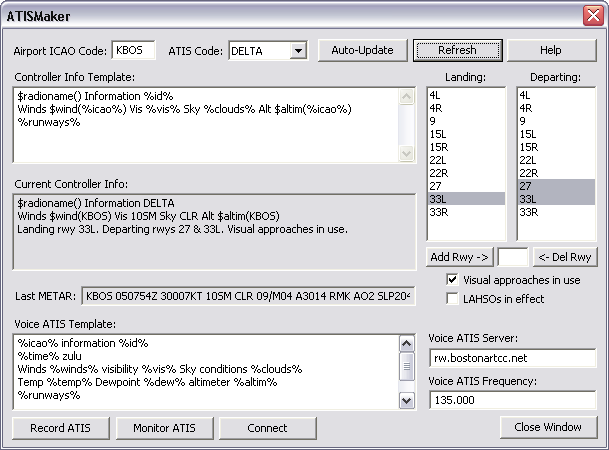
Initially, the Airport ICAO box will be empty, and the runway lists will be empty. You will need to enter the ICAO code for the field where you will be working. You will also need to enter the list of runways. Once you have done this, you should save your profile so that you don't have to repeat the process the next time you work the same field.
To enter runways, enter the runway identifier in the box provided, and press the "Add Rwy ->" button. The runways are added to the list in the order you enter them. If you make a mistake and you want to remove a runway, enter its identifier and press the "<- Del Rwy" button.
The next thing you need to configure is the ATIS Template. The template text is used by ATISMaker to construct your ATIS when required. You can use all of the normal ATIS variables and functions as listed above, plus there are some new variables that only have meaning when used in the ATISMaker template. These variables are listed below:
|
Any of the above variables will be replaced with their actual value whenever ATISMaker generates your ATIS. There are a number of situations which cause ATISMaker to update your ATIS. The first is by manually pressing the "Generate ATIS Now" button. This will cause ATISMaker to fetch the latest METAR for the specified field, insert the appropriate variables into your template, and copy the resulting text to your actual ATIS which will be sent to pilots.
Your ATIS is also updated by ATISMaker when you manually choose a new ATIS identifier from the "ATIS code" dropdown list.
Finally, your ATIS will also be updated if you place ATISMaker in "Auto" mode and a new METAR is received by VRC. (VRC checks for new METARs every five minutes.) To place ATISMaker in Auto mode, press the "Auto" button. The button will remain depressed while in Auto mode. If a new METAR is recieved, ATISMaker will automatically switch to the next ATIS identifier and update your ATIS. The ATIS identifier will flash in the Button Bar to alert you that a new ATIS is available.
Note that any time you place ATISMaker in Auto mode, or manually choose an ATIS identifier from the dropdown list, the current ATIS identifier will be shown in the Button Bar on the Primary Display.
Selecting the Active Runways
If you use the %runways% variable in your template, ATISMaker will build a sentence listing the selected arrival and departure runways and insert it into the template in place of the %runways% variable. To select the active runways, simply click on the runway identifier in the appropriate list. The entry will be highlighted in gray if it is selected. As an example, in the above screenshot, runway 33L is active for arrivals, and runway 15R is active for departures. This would cause ATISMaker to replace %runways% with "Landing rwy 33L. Departing rwy 15R." in your template. Experiment with different combinations of active runways to learn how the information is portrayed in your ATIS.
Other ATISMaker Settings
ATISMaker also provides checkboxes which allow you to indicate whether or not visual approaches are in use, and whether or not Land And Hold Short Operations (LAHSOs) are in effect. If you check these boxes, ATISMaker will add text to the list of active runways in order to pass on the information to pilots. Experiment with checking these boxes to see the effect on your ATIS.
Remember to save your profile when you are done working with ATISMaker.
Voice ATIS
Starting with version 1.2, VRC supports the ability to provide your ATIS information as an audio recording, just like real-world ATISes.
To create a voice ATIS, you must first create a Voice ATIS template. The template box is shown on the ATISMaker window just below the "Last METAR" box. Default Voice ATIS template text is provided if you have not previously configured it. You use all the same variables and functions as you use for creating your regular Controller Info template.
When you are ready to record your voice ATIS message, press the "Record ATIS button". A window will be shown containing your voice ATIS template with all the variables filled in:
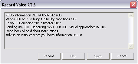
This text is called the Voice ATIS "script". Review the script to make sure the information is correct, then press the "Record" button and begin speaking. Leave a few seconds of silence at the end of your message before pressing the Record button again to stop the recording.
Next, press the "Play" button to listen to your recording. Press the play button again to stop the playback. If you wish to re-record the message, press the Record button again. Your previous recording will be overwritten. Once you are happy with the recording, press the "Save" button. If you decide not to record a new voice ATIS message, press the "Cancel" button.
After saving your recording, you can then connect your voice ATIS to the VATSIM network. First, be sure to enter the appropriate server address in the "Voice ATIS Server" box. Your local instructional staff will tell you what to use here. Also, enter the correct radio frequency for the airport in the "Voice ATIS Frequency" box. This frequency can usually be found on airport diagrams or other charts.
When you are ready to connect your voice ATIS, press the "Connect" button. The button will be temporarily disabled while the connection is made. Once the connection is created, the Connect button will be changed to read "Disconnect". Press the Disconnect button to disconnect your voice ATIS from the network.
If the conection is made successfully, you will see a new entry in your Controller List representing your voice ATIS. For example, if you are creating a voice ATIS for KBOS, you will see "KBOS_ATIS" appear in the controller list. This is your voice ATIS connection. It appears on the network as a separate "controller" with its own primary frequency and voice channel. Pilots will see this entry in their list of in-range controllers once they are within radio range of your airfield. If a pilot tunes your voice ATIS frequency, they will hear your message looped repeatedly until they tune a different frequency. Note that VRC only transmits your recording to the voice server if there is at least one pilot listening in on the frequency.
During your session, when the weather changes, you will need to update your voice ATIS message. You can do so at any time, even if you already have an active voice ATIS connection. Your existing voice ATIS recording will remain in effect while you are recording the new message. The new recording will replace the current one once you press the Save button on the recording window.
After recording and saving your message, you can listen to it by pressing the "Monitor ATIS" button on the ATISMaker window. Press the same button again to stop monitoring the recording.
While you have an active voice ATIS connection, a small green "v" will appear in the ATIS button in your button bar. If for any reason the voice server connection fails, the v will turn red and begin blinking. If this happens, disconnect your voice ATIS and check the voice server address in the ATISMaker window.
Note that the voice ATIS script also serves as the text version of your voice ATIS. This text will be shown to pilots when they tune your ATIS frequency. Your regular Controller Info (described at the beginning of this page) is still maintained separately using the Controller Info Template. Your controller Info will be displayed to pilots when they tune your primary frequency, and your voice ATIS script will be shown to pilots when they tune your voice ATIS frequency.
Connecting to VATSIM
After loading VRC and choosing a profile (See "The Profile System") the next thing you will normally do is connect to the VATSIM network. To do so, choose "Connect..." from the "File" menu. You will then see the Connect window:
If you have previously connected and saved the connect information in a profile, the boxes on the Connect window will already be filled in. Take a quick look to make sure everything is correct, then press the "Connect" button.
After pressing the Connect button, the Connect window will close, and VRC will attempt to connect to the VATSIM network using the information you just provided. Text messages will be shown in the Primary Display telling you whether or not the connection succeeded. Normally, the connection will happen instantly, and you will see some welcome messages from the server. The Primary and Secondary Display title bars will also be updated to show which server you are connected to.
Assuming no errors are shown, you are now connected to VATSIM. You will begin to see aircraft targets appear on the scope if any are in range. You will also see any in-range observers and controllers appear in the CL.
Navigating the Scope
VRC provides a few different ways to alter the view presented to you in the Display Windows. The scope can be smoothly panned using the mouse, zoomed in and out, or instantly recentered using keyboard commands. See the sections below for details:
Recentering the Scope
There are four ways to change the center point of a scope. The most common way is by panning. To pan the scope, click and hold the right mouse button, and move the mouse. The radar display will move along with the mouse as though you were sliding a map around on a table.
The second way to recenter the scope is by double-right-clicking on any point. The scope will instantly recenter on that point. This is handy for taking a quick look at a certain spot such as a cluster of aircraft in order to get a closer look at their tags.
The third way is by using the .center command. To use this command, enter it on the command line followed by the name of an airport, VOR, NDB or intersection. The scope will instantly recenter on the specified fix. For example:
.center KBOS
This command will center the Primary Display on the KBOS airport.
Finally, you can also recenter the scope by recalling a bookmark. See the section on bookmarks below for details.
Zooming the Scope
There are three ways to zoom the scope in and out. The first and most common method is by rotating the mouse wheel. While doing so, if you are holding the CTRL key down, the zooming will be much faster, allowing you to very quickly zoom in on a small area such as an airport, if you were previously zoomed far out working a large sector.
The other method for zooming the scope is to use the F11 and F12 keys. These keys zoom in and out respectively.
You can also change the zoom level for the scope by recalling a bookmark. See the section on bookmarks below for details.
Bookmarks
While working just about any position from Tower on up to Center, you will find yourself needing to zoom and pan the scope a lot in order to get a look at different parts of your airspace. When it gets busy, especially in the larger sectors, this zooming and panning can get tedious and repetitive. For this reason, VRC provides a feature known as bookmarks. A bookmark is a way of telling VRC to remember the current zoom level and center point for the scope, so that you can very quickly "snap" back to that view by recalling the bookmark. Bookmarks also include the center point for the range rings.
To set a new bookmark, press CTRL+ALT+n where n is the bookmark number you wish to save. You can store up to nine bookmarks in a single profile. To set your first bookmark, press CTRL+ALT+1. To set your second bookmark, press CTRL+ALT+2 and so on.
To recall a bookmark, press CTRL-n where n is the bookmark number. The scope will be instantly recentered to the point where it was centered when you set the bookmark. The zoom level will also be set to match the zoom level from when the bookmark was set. Also, the range rings will be recentered on the same point where they were.
Note that bookmark 0 (zero) is a special case. You cannot manually set bookmark zero. It is automatically set whenever you recall a previously-saved bookmark. That way, you can use a bookmark to take a quick look at a certain spot on the scope, then press CTRL-0 to return to the exact view you had just before you recalled the bookmark.
Note that bookmarks only work in the Primary Display. Remember to save your profile after setting a bookmark in order to retain the setting for the next time you use the profile.
Organizing Datablocks
Note that you can reposition an aircraft's datablock by clicking and dragging it. This only applies if the aircraft has been "tagged up". (See "Tagging-up an Aircraft".) This is very handy when there are a lot of aircraft on the screen in close proximity and their tags begin to overlap.
The Various Radar Modes
As of version 1.1, VRC offers ten different radar modes:
- Simple
- Ground
- Tower
- ARTS (Approach)
- STARS (Approach)
- DSR (Enroute/Center)
- VRC
- Park Air
- TAAATS
- PSR
- 3D
To switch among these modes, choose "Radar Mode" from the "Settings" menu. This will display a sub-menu containing the ten modes.
If you have used ASRC, then you are familiar with some of these modes. The "VRC" mode, however, is obviously unique to VRC. It is essentially a combination of the ARTS and DSR modes. New modes in VRC 1.1 include Simple, Park Air, TAAATS, PSR and 3D. Detailed descriptions of each mode are found below.
Simple Mode
This mode is mainly intended to be used by Clearance Delivery controllers. Only the aircraft callsign is shown. In VRC 1.0, this mode was called the Ground mode. Here are the different types of tags you'll see in Simple mode:
|
Ground Mode
As the name implies, this mode is meant to be used by ground controllers. Tags include the callsign, aircraft type, and ground speed. Here are the different types of tags you'll see in Ground mode:
|
Tower Mode
As the name implies, this mode is meant to be used by Tower controllers. It is very similar to the ARTS mode (see below) except all targets always have a full data block, even if they are squawking standby. Here are the different types of tags you'll see in Tower mode, along with a description of the data in the tag:
|
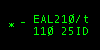
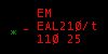
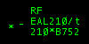
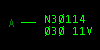
ARTS Mode
ARTS mode is similar to the radar modes used in many TRACONs. ARTS and Tower modes are very similar, except that with ARTS mode, aircraft can have either partial or full data blocks. Also, if a target is squawking standby, you'll see no data block at all in ARTS mode. Here are examples of the differences between the ARTS and Tower modes:
|

STARS Mode
STARS mode is very similar to ARTS mode. The primary difference is that the data in the tag rotates at a slower rate, and the primary target symbol is a line that is drawn perpendicular to the closest radar station (defined by your visibility center(s) and changes in size based on distance from that station. Also, when identing, the aircraft's full data tag flashes, instead of just part of it as in ARTS mode.
DSR Mode
DSR mode resembles the radar system used in many enroute traffic control centers. Full data blocks have three lines instead of two. Also, additional information is shown regarding the aircraft's altitude, such as whether or not it has reached its filed cruise altitude, or if it is currently climbing or descending. DSR mode also shows the aircraft CID (computer ID) in the data block. The CID provides another way to select aircraft. (See "Selecting Aircraft".) Here are the different types of tags you'll find in DSR mode:
|
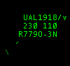
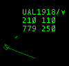
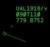
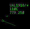
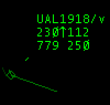
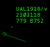
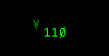

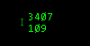
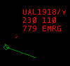
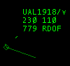
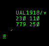
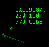
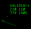
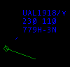
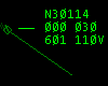
VRC Mode
The VRC radar mode is not modelled after any real-world radar system. It was designed to show certain pieces of information at all times, while rotating the less-critical data items in a single field. The main idea is to have the altitude, ground speed, and aircraft type available at a quick glance without having to wait for them to rotate into view. Here are the different types of tags you'll encounter in VRC mode:
|
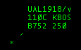
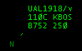
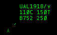
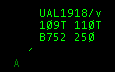
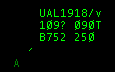
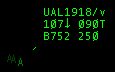
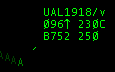


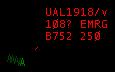
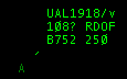
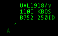
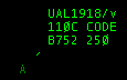
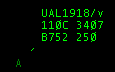
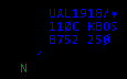
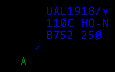
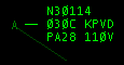
Park Air Mode
The Park Air radar mode simulates the radars used by many approach controls in the UK. Here are the different types of tags you'll encounter in Park Air mode:
|
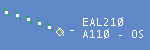


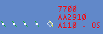

TAAATS Mode
The TAAATS Radar Mode simulates the look of the Australian Air Traffic Control System. Based on Eurocat, it uses colours and shapes differently from traditional radar to provide more information on the state of each aircraft. While it is impossible to mimic the consoles exactly, many key features and components are simulated in this mode.
Key Differences:
- All targets with transponder on (Mode C) will be tagged (unless the filter is used to supress them)
- Colours are used to indicate ownership. NOTE: Colours are hardcoded at this time
- Target shapes are used to indicate tracking modes and flight state
- Mouse Wheel-click on callsign toggles between full and limited datablock
- Voice flag is shown in last (expanded) line of datablock
|
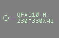
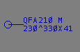
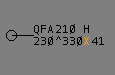
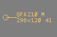
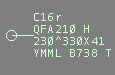
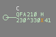
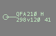
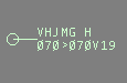
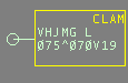
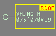
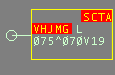
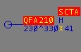
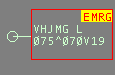
PSR Mode
PSR stands for "Primary Surveillance Radar". In this mode, only a primary radar return is shown, depicted as a slash. This primary return is also known as a "skin paint". It is a representation of the radar energy being bounced back to the radar antenna by the fuselage of the aircraft. This mode is intended for controllers using special procedures for facilities that only have basic radar and no SSR (Secondary Surveillance Radar) systems with which target callsign and flight plan data can be correlated.
|
3D Mode
The VRC 3D radar mode is quite different from the other radar modes. Whereas the other modes provide a "top down" view, the 3D mode provides a three-dimensional view of your airspace and sector file information. This mode is ideal for providing a very simple "out-the-window" view for Tower and Ground controllers.
You are able to pan the camera by holding down the right mouse button and moving the mouse. You can also zoom the camera in and out using the mouse wheel. If you wish to move the location of the camera, hold both the left and right mouse buttons, and move the mouse. You can raise and lower the camera height by holding the CTRL key and rotating the mouse wheel. The .set3dalt command can also be used to set the camera altitude. For example, the following command will set the camera altitude to 300 feet:
.set3dalt 300
You can set the terrain height as well. The terrain height is the altitude MSL at which all the data in your sector file are drawn. You should set this to the airport elevation for the field where you are controlling. The command to set the terrain height to 1200 feet would be:
.setterrainalt 1200
You can also use a dot command to move the camera to a specified location. For example, to move the camera to the Manchester VOR, you would use the following command:
.set3dcenter MHT
You can also lock the camera onto a specific target using the .lockview command. For example, if you wanted to lock the camera onto the currently selected aircraft, you would type .lockview followed by pressing your aircraft select key. To unlock your view, simply type .lockview followed by the Enter key.
The targets in 3D mode have simple one-line data tags that rotate between the callsign, the altitude and speed, and the aircraft type and destination. Note that targets and tags are not clickable in 3D mode. You'll need to use another scope window, the strip bay, or the ASEL key to select aircraft on a 3D mode scope.
|
Notes
- If you have multiple Display Windows open, you can set the radar mode separately in each one.
- In all modes that have a datablock, you can reposition any aircraft's datablock by clicking and dragging it.
- The colors used in the TAAATS and Park Air radar modes are hardcoded. Changes to your color selections will not affect these modes.
Opening Additional Displays
VRC allows you to open more than one scope window at a time. These are called "Secondary Displays". Each Secondary Display can have its own sector file, its own options selected in the "View" menu, its own visible diagrams, and its own radar mode.
Secondary Displays are most useful when working an enroute position. You might open a secondary display for any major airports within your sector, so that you could easily watch traffic on the ground at the airport, or just to get a closer look at the approach area in order to vector arrivals. Secondary Displays are also handy for Tower controllers. You could have one display showing a close-up view of the runways and taxiways, and another display showing a wider view including the approach path to the active runway.
To open a Secondary Display, choose "New Window" from the "File" menu. A new window is opened in the default location, which is the top-left corner of your primary desktop. The new window defaults to a size of 640x480. It will automatically have the same sector file and configuration as the Primary Display, but you can easily change the sector file, radar mode, and display configuration via the menus on the new window.
You will notice that Secondary Displays do not have some of the features of the Primary Display, such as the Button Bar, the Radio History area, and the Command Line. This is because Secondary Displays are generally kept smaller than the Primary Display, and thus they are kept as clutter-free as possible.
After opening the new window, it can be resized and dragged to a new position. If you would like to retain the display configurations for a future session, remember to save your profile. Secondary Displays, as well as their size, position and configuration are stored in the profile.
Sending Commands to Secondary Displays
Since Secondary Displays do not have a command line, VRC includes a special command syntax for sending commands to them. To do so, follow the command with a slash, followed by the Display ID. The Display ID is shown as the first item in the Display's title bar. In the following example screenshot, the Display ID is 3:
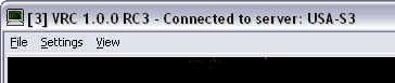
In order to send a command to this display for processing, you would follow the command name with "/3". For example, if you wanted to turn on the display of the KBOS runway 33L ILS approach fixes, you would issue the following command:
.ff /3 HULLZ COHAS BENNN
This would toggle the display of those three fixes on Display 3.
This syntax works for any command, but only some commands are actually specific for Display Windows. In other words, it wouldn't make any sense to use this syntax for the .break command, but it will still work. Generally, this syntax would only be used for toggling sector data items (as in the example above), setting a scope's center point, positioning the range rings, setting visibility centers, etc.
To close a Secondary Display, either choose "Close Window" from the "File" menu, or click the X icon at the top-right corner of the window.
Also note that if you close a Secondary Display window, the Display ID for other windows remain the same. They are not renumbered to "fill the gap" in the sequence that you may have created by closing a Display. However, if you save your profile, then reload it later, the Display windows will be numbered in order.
Remember to save your profile if you wish to save the number and configuration of your Display windows.
Selecting Aircraft
The single most important function in VRC is the ability to "select" an aircraft. This is because most of the commands you type on the command line, as well as many of the mouse-related functions, are all performed on the currently selected aircraft. The currently selected aircraft callsign is shown just to the left of the Command Line. The Command Line is found at the bottom of the Primary Display. Here's a screenshot:
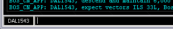
In this screenshot, the currently selected aircraft is DAL1543. There are several ways to select an aircraft:
- Click on the aircraft's target (not its data block) in the scope. This is called "slewing" the target.
- Type part of the aircraft's callsign and press your configured ASEL key. (See "Configuring VRC")
- Type the letter or number associated with the aircraft in the Aircraft List and press your ASEL key. (See "The Aircraft List")
- Type the three-digit computer ID for the aircraft (as shown in the DSR radar mode) followed by a slash, then press your ASEL key.
- Double-click a flight strip for the aircraft in the Flight Strip Bay. (See "The Flight Strip Bay")
- Type the command, followed by the aircraft's Computer ID (CID) and press Enter.
Log on to VATSIM and experiment with these different methods. Certain methods work better than others depending on the situation.
Once you have selected the aircraft you wish to work with, you can then issue commands and send textual radio message to that pilot without having to re-select the aircraft each time. It's a good idea to get into the habit of glancing at the command line to see which aircraft is currently selected before sending a command or a text message so that you don't inadvertently work with the wrong aircraft.
Working With the Command Line
When working with aircraft, almost every function is performed via the Command Line. The Command Line is found at the bottom of the Primary Display. The Command Line is also used to send textual radio messages to aircraft. It is also used for many miscellaneous functions within VRC via the various dot commands. (See the Command Reference for a complete list.) Here's a screenshot of the Command Line with a command being typed in by the user:
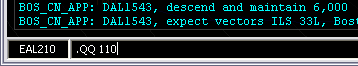
In this screenshot, the currently selected aircraft is EAL210, and the user is typing the command .QQ 110. This is dot command used for assigning a temporary altitude to an aircraft. Once the user presses enter, the temporary altitude of FL110 will be assigned to EAL210.
The VRC Command Line works like most text boxes in the Windows environment. You can use all the same shortcut key combinations in order to do various things like selecting text, moving the cursor to the beginning or end of the line, etc. You can also use CTRL+C and CTRL+V to copy and paste text in the Command Line. Here are some additional keyboard functions that work with the VRC Command Line:
- Esc - Clears the contents of the Command Line or unselects the currently selected aircraft if the Command Line is already empty.
- Up Arrow - Retrieves the last-entered command by scrolling backward in the command history.
- Down Arrow - Scrolls forward in the command history.
Sending Text Radio Messages
The Command Line is also used for sending radio messages to pilots via text. You may need to do this if you have a problem with voice communications or if you need to work with a text-only pilot. To send a text radio message to a pilot, simply type the message on the Command Line and press Enter while you have the aircraft selected. The message will be sent with the aircraft's callsign prepended to the message. This will cause a sound to be played for the pilot when he receives the message. Note that if you do not have any aircraft selected when you send a text radio message, the sound will not be played for any pilot, but the message will still go out over the text frequency.
Note that any text radio message that you send will go out on not only your primary frequency, but also on any secondary frequencies that you have selected for transmit on the Communications Panel.
Using Aliases
VRC provides the ability to use aliases to help save you from always having to type out messages that you commonly send to pilots, such as IFR clearances and common instructions. Aliases are defined in your alias file (See "Configuring VRC") which you can get from the training staff in the area where you will be controlling. See "Communicating with Pilots" for details on using aliases.
Sending ATC Messages
ATC messages are like text radio messages, except they go to all controllers and observers within your range, instead of going out on a text radio frequency. To send an ATC message, prefix the message with a forward slash (/) in the command line, such as "/Boston Center online, 134.7".
Chat Windows
All private messages in VRC are viewed in Chat Windows. You can have multiple Chat Windows open, including Group Chat Windows. When you receive a private message from a pilot or a controller, the associated entry in the Controller List is highlighted in blue. To view the message, double-click on the entry. This causes a chat window to be displayed. Here's an example screenshot:
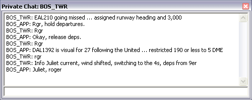
Any message you type in a private chat window will be sent only to the recipient, which is BOS_TWR in the example screenshot shown above.
Here's an example of what a Group Chat window looks like:
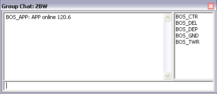
The members of a group chat are listed at the right side of the window. Any text sent via the group chat window will be sent as private messages to each recipient in the chat. Note that any chat received from a member of a group chat will not necessarily be sent to the other members of your group chat. That would only happen if the sender also had the same members in a group chat and sent his message via that group chat window.
To close a chat window, type .x or click the X icon in the upper right corner. Any messages in the chat history area of the chat window will be discarded.
To hide a chat window, press Esc while the keyboard focus is on the chat window. Any messages in the chat history area will be retained and redisplayed when you re-open the chat window by double-clicking on the appropriate entry in the Controller List. Like most Tool Windows in VRC, chat windows can be "rolled up" so that only the title bar is visible. To do so, double-click in the title bar. Double-click again to unroll the window.
The following dot commands are available within chat windows:
|
Blocking Private Messages
If you are very busy, you might find that incoming chat messages are too distracting. VRC provides the "busy mode" to help deal with this. When you are in busy mode, incoming chat messages are blocked, and a message is sent back to the sender. You can set busy mode for pilots only or for both pilots and controllers.
To set busy mode for pilots only, type .busy I'm not accepting private messages at this time or something similar. You can specify any message you like. The message is optional ... if you do not specify a message, VRC will instead send a message similar to the one shown here in the example. Note that while in busy mode, your callsign is shown in red in the clock button.
To set busy mode for both pilots and controllers, use the .busyall command instead.
To unset busy mode, use the .nobusy command.
Note that VRC cannot make a distinction between pilots and out-of-range controllers. In other words, only controllers within your visibility range will be able to send you private chat messages when you are in busy mode (and not busyall mode.)
Saving Chat Logs & Copy/Paste
VRC provides a few ways to save the contents of a chat window. The first way is by selecting it with your mouse. If you click and drag your mouse across a selection of text, that text will be copied to your Windows clipboard when you release the mouse button. You can then paste the text into another chat window, or into a text file or email, etc.
You can also type the .copy command which will copy the entire contents of the chat window history into your clipboard.
Finally, you can use the .log FILENAME command to save the chat history to a file with the specified name. For example, enter the command .log DAL123.log to save your current chat log in a file called "DAL123.log". This file will be located in your "My Documents\VRC" folder.
Miscellaneous Notes
You can retrieve a controller's ATIS via a private chat window by double-clicking on the chat history area.
Note that if you have unread private messages from one or more senders, and you create a chat group with those senders (or add them to an existing chat group), their unread messages will be copied to the group window. Note that the messages will not necessarily be in chronological order.
Another way to open a chat window is by typing the one or two character ID from the Controller List into the main command line, then pressing your CSEL (Controller Select) key.
Communicating with Pilots
There are three ways to communicate with pilots on VATSIM:
- Via textual radio messages on a frequency
- Through a voice channel
- Via private text messages
Normally, communications happen over voice or text on a frequency. Private messages should only be used for communications that wouldn't normally be heard over the open frequency in the real world.
Setting Your Primary Frequency
When you are "plugged in" and actively controlling, you must select a primary frequency. Your primary frequency is the one pilots will dial into their COM radio in order to contact you. It is the frequency that is usually listed in the pilot software in their list of available controllers. Setting your primary frequency is the first thing you need to do after connecting to VATSIM as an active controller. If you are only connecting as an Observer, then you do not need to select a primary frequency. See "The Comms Panel" for details on configuring your available frequencies and selecting your primary frequency.
Secondary Frequencies
In addition to your primary frequency, you can also receive and optionally transmit on additional frequencies. This can be useful if you are working with a student and you want to monitor his/her transmissions and other radio traffic. This applies to both text frequencies and voice channels. See "The Comms Panel" for details on choosing which frequencies to use via text and/or voice.
The Radio History Area
Any text sent by you or received from pilots is displayed in the Radio History Area. The Radio History is found only on your Primary Display, just above the command line. This area is also used to show miscellaneous messages from VRC, ATC messages, supervisor broadcasts, server messages, etc.
Text sent by you will be displayed in cyan. Text received from pilots on your primary frequency will be shown in white. Text received from pilots on secondary frequencies will be shown in gray.
You can change the size of the Radio History Area using CTRL+Up Arrow and CTRL+Down Arrow. These will increase and decrease the size of the Radio History one line at a time. If you would like to temporarily expand the Radio History Area to fill the scope, you can presss CTRL+Tab. Press CTRL+Tab again to return the Radio History to it's normal size. This is handy for making a quick review of received messages if you had to step away for a moment or if you are quite busy and missed a call.
Note that the gray border around the Radio History Area will flash white when a radio message comes in on your primary frequency. To acknowledge the message and stop the flashing, you can either click on the Radio History Area, press CTRL-Space, or send a message. This feature can be turned off in the General Settings. (See "Configuring VRC".)
Saving Radio Logs & Copy/Paste
VRC provides two ways to save the contents of your radio history. The first is by typing the .copy command which will copy the entire contents of the radio history into your Windows clipboard. You can then paste the log text into a text file, email, etc.
You can also use the .log FILENAME command to save the radio history to a file with the specified name. For example, enter the command .log radio.log to save your current radio history text in a file called "radio.log". This file will be located in your "My Documents\VRC" folder.
Frequency Buttons on the Button Bar
For each frequency you are using, a frequency button appears in the Button Bar, if frequency buttons are enabled. (See "Configuring VRC".) A frequency button looks like this:

The yellow number is the frequency. Below that, you will see text that indicates the voice status of the frequency. The status text will contain one of the following:
- ON HDST - The voice channel associated with this frequency in your comms panel is being routed to your headset device.
- ON SPKR - The voice channel associated with this frequency in your comms panel is being routed to your speaker device.
- TXT ONLY - You are not currently connected to the voice channel associated with this frequency.
- MUTED - You are connected to the voice channel, but it is currently muted. Click the button to turn muting on or off.
The TX and RX lights on the frequency button indicate whether or not you are set to transmit or receive on the indicated frequency, via text or voice, and whether or not you or someone else is currently transmitting voice on the frequency. Here are some example screenshots with descriptions of what the information on the button means:
|


See "The Comms Panel" for details on configuring your available frequencies and selecting your primary frequency.
Aliases
When communicating with pilots via text, you will often be repeating similar clearances and instructions many times over. VRC provides a way to create shortcuts that can save you a great deal of typing and help ensure that your text phraseology is accurate. These shortcuts are known as "aliases". An alias is a short dot command that gets expanded into a longer string of text before it is sent to pilots. Aliases are defined and stored in your Alias File, which is specified in the General Settings. (See "Configuring VRC" for details.) Contact the training staff in the area where you will be controlling to acquire the appropriate alias file.
Here's an example of a common alias:
.dm descend and maintain $1
If this alias is present in your alias file, and you type .dm 6000 on the command line and press Enter, the following text will be sent on your active transmit frequencies:
descend and maintain 6000
Notice the $1 was replaced with the first parameter you typed after the alias name. Up to nine parameters ($1 through $9) can be used in alias definitions. Here's an example of an alias which uses more than one parameter:
.trd Turn right heading $1, proceed direct $2 when able
To use this alias, you might type .trd 350 MHT. The resulting text sent on the frequency would be:
Turn right heading 350, proceed direct MHT when able
As you can see, aliases can save you a great deal of typing and help ensure accurate phraseology when working with text-only pilots.
Alias Variables
In addition to substituting parameters using $1, $2, etc., there are also variables and functions available for creating more complex aliases. A variable is a special word, preceded with a dollar sign, that is replaced with an appropriate value before the text is sent on the frequency. As an example, the variable "$squawk", if present in an alias, will be replaced with the pilot's currently assigned squawk code before the text of the alias is sent to the pilot. So if you had the following alias defined:
.sq Reset transponder, squawk $squawk and ident
And you typed .sq and pressed Enter, and the selected aircraft was assigned 3405 as its squawk code, the following text would be sent:
Reset transponder, squawk 3405 and ident
The following table lists all of the variables available to you when constructing aliases:
|
Alias Functions
VRC also provides several functions for inserting information into transmitted text. A function differs from a variable in that a function can accept a parameter to alter the text that is inserted in place of the function. The following table lists all of the functions available when constructing an alias:
|
Here's an example of a function used in an alias:
.initvec Fly heading $1, .dm $2, vectors ILS runway $3 approach, $4 altimeter $altim($4)
To use this example alias, you might type .initvec 070 6000 33L KBOS
This would result in the following text being sent on the frequency:
Fly heading 070, descend and maintain 6000, vectors ILS runway 33L approach, KBOS altimeter 2975
Notice that this is a nested alias. A nested alias is one which uses additional aliases in its text. In the above example, the .dm alias is nested within the .initvec alias. You can nest as many aliases as you like within a single alias.
To get a better idea of the possibilities for creating aliases, study the alias file provided to you during your training.
"Tagging-up" an Aircraft
When using the DSR, ARTS or VRC radar modes, aircraft normally start out with a limited data block. (LDB) The LDB shows the minimum information about a target, such as squawk code and altitude. In order to see more information about the aircraft, you need to switch to a full data block, or FDB. This is called "tagging-up" the target. It can be done manually or automatically depending on the situation.
To manually tag-up an aircraft, press F1, then slew the target. (Click on it.) You can also use your ASEL key after pressing F1 if you already have the aircraft selected. See "Selecting Aircraft" for details on selecting aircraft.
There are two situations in which aircraft will automatically tag-up. The first is if they depart a field that you have listed in your departure fields. (See "Configuring VRC" for details.) The other way is by assigning a squawk code to the aircraft. Once the aircraft switches to the assigned squawk code, it will automatically tag-up.
Note that you can reposition an aircraft's datablock by clicking and dragging it.
Viewing & Editing Flight Plans
As a controller, a large part of your job involves reviewing and editing aircraft flight plans. In VRC, this is done through the Flight Plan Editor window, shown here:
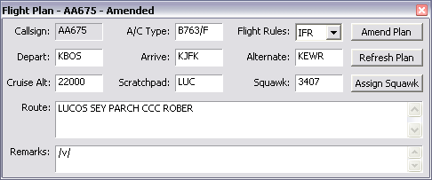
To open an aircraft's flight plan in the Flight Plan Editor, press F6 and then slew the target. Or, if you already have the aircraft selected, press F6 followed by your ASEL key. Another way is to hold the CTRL key and slew the target.
All fields in the flight plan window are editable, except for the callsign. The only way for a pilot to change his callsign is to disconnect and reconnect with the new one.
After making changes to any of the information on the screen, press the "Amend Plan" button to save your changes and submit the amended flight plan to the network.
Note that if you include "/v/", "/t/" or "/r/" in the remarks field, VRC (and ASRC) will automatically show the appropriate voice type tag in the datablock for the aircraft.
To retrieve a fresh copy of the flight plan from the server, press the "Refresh Plan" button.
You can also assign a squawk code to the aircraft using the Flight Plan Editor window. If you enter a new squawk code while revising other fields in window, followed by pressing the "Amend Plan" button, the new squawk code will be assigned to the aircraft. Alternatively, you can just assign a squawk code without making any changes to the flight plan. To do so, enter the squawk code and press the "Assign Squawk" button. This will assign the squawk code you typed into the field, without amending the flight plan. You can also just press the Assign Squawk button without typing a code into the box, and VRC will choose a new squawk code for you, based on the code range specified for your position in the currently-loaded POF file.
To close the Flight Plan Editor window, press Esc or click the X icon in the top right corner.
Note that you cannot amend the flight plan for an aircraft if another controller is tracking it.
Assigning a Squawk Code
One of the most common things you'll do when working with aircraft is assigning squawk codes. A squawk code (a.k.a. transponder code) is a four digit number which uniquely identifies the aircraft on the network. Assigning a squawk code is also one of the primary ways controllers can "radar identify" a target. There are several ways to assign a squawk to an aircraft in VRC:
- Press F9 and slew the target.
- Select the target, press F9, then press your ASEL key.
- Use the button on the Flight Plan Editor window. (See "Viewing & Editing Flight Plans")
All of the above methods will assign a code based on the code range specified for your position in the currently-loaded POF file. If you would rather assign a specific code, then you can either enter the code into the appropriate field on the Flight Plan Editor window and press the "Assign Squawk" button, or you can press F9, enter the code, then slew the target or press ASEL if the aircraft is already selected.
Note that if you allow VRC to automatically choose the squawk code (this is the most common method) then a code will be chosen from the range specified in your POF file, but VRC will automatically skip over any codes that have already been assigned to aircraft within range (by you or any other controller) as well as codes that are already being squawked by aircraft within range. VRC keeps track of the last code that it assigned from your code range, and uses the codes in order until reaching the end of the range, then starts from the beginning again.
Note that you cannot assign a squawk code to an aircraft if another controller is tracking it.
Assigning Temp and Cruise Altitudes
Another common function you will perform when working with aircraft is assigning altitudes. There are two types of altitudes you can assign to an aircraft while it is under your control. They are the cruise altitude and the temporary altitude.
The cruise altitude is assigned by the controller when the aircraft needs to be given a new cruise altitude which will remain in effect for the remainder of the flight. For example, this often happens if the pilot reports turbulence at his filed cruise level and requests a new one.
To assign a new cruise altitude to an aircraft, press the F5 key, type the new altitude in hundreds of feet, then slew the target or press the ASEL key if the aircraft is already selected. The new cruise altitude will be displayed in the aircraft's datablock (if applicable) and updated in the Flight Plan Editor window or flight strip if you have either of those visible for the aircraft.
Temporary altitudes are used when you need to restrict an aircraft to a certain altitude for the time being, but you intend to assign a new altitude or clear the aircraft to its filed cruise altitude later. An example would be when an aircraft is climbing to its cruise altitude, but will possibly conflict with another aircraft during the climb. In this case, you might assign a temporary altitude for the aircraft to maintain until the potential conflict has passed.
To assign a temporary altitude to an aircraft, press the F8 key, type the new altitude in hundreds of feet, then slew the target or press the ASEL key if the aircraft is already selected. The new temp altitude will be displayed in the aircraft's datablock (if applicable) and updated in the Flight Plan Editor window or flight strip if you have either of those visible for the aircraft.
To clear a temporary altitude assignment, press the F8 key then slew the target or press your ASEL key if the aircraft is already selected.
The cruise altitude can also be assigned via the Flight Plan Editor window. (See "Viewing & Editing Flight Plans" for details.)
Note that assigned cruise and temporary altitudes are automatically propagated to other controllers.
Note that you can only assign altitudes to aircraft that are not already being tracked by another controller.
Setting the Scratchpad
VRC supports the use of the "scratchpad" feature on VATSIM. The scratchpad is a small chunk of arbitrary text that can be inserted into the aircraft's flight plan and data block by the controller. It is often used to communicate bits of information to adjacent controllers. For example, some facilities use the scratchpad to indicate which approach the pilot has requested, or which transition on the departure procedure the aircraft will be using.
To set the scratchpad for an aircraft, press the Insert key, type the new scratchpad value, then slew the target or press the ASEL key if the aircraft is already selected. The new scratchpad text will be displayed in the aircraft's datablock (if applicable) and updated in the Flight Plan Editor window or flight strip if you have either of those visible for the aircraft.
To clear the scratchpad for an aircraft, press the Insert key then slew the target or press your ASEL key if the aircraft is already selected.
The scratchpad can also be set via the Flight Plan Editor window. (See "Viewing & Editing Flight Plans" for details.)
Note that the scratchpad text is automatically propagated to other controllers.
Note that you can only assign the scratchpad text for aircraft that are not already being tracked by another controller.
Setting the Voice Type
On VATSIM, not all pilots have the ability or desire to communicate with controllers via voice. These pilots will communicate with you via text. Most pilots will indicate via the remarks field in their flight plan whether or not they will be using text or voice. The accepted standard for notating the voice capability in the remarks is as follows:
- /v/ - The pilot is on voice.
- /t/ - The pilot is on text.
- /r/ - The pilot can receive via voice, but responds via text.
When a new pilot appears on your scope, VRC checks the flight plan remarks for one of the above notations. If one is found, the aircraft's datablock is tagged with a voice type indicator. This tag is shown just after the callsign on the first line of the data tag. It will either be /v, /t, or /r accordingly. An example of a text-only pilot is shown here:
If the pilot does not have his/her voice type indicated in the remarks, you can manually set the voice type tag for the aircraft's datablock by pressing F9 followed by either v, t, or r, followed by slewing the target or by pressing the ASEL key if the aircraft is already selected.
Note that you cannot use the F9 key to override the voice type indicated in the flight plan remarks. If the voice type is in the remarks, and you wish to alter it, simply change the remarks in the Flight Plan Editor window and press the "Amend Plan" button. See "Viewing & Editing Flight Plans" for details.
Note that the voice type tag is automatically propagated to other controllers.
Note that you can only assign voice type tags to aircraft that are not already being tracked by another controller.
Tracking Targets
When working a radar position such as Approach, Departure or Center (and sometimes Tower and even Ground), you will be "tracking" any aircraft under your control. VRC allows you to initiate and drop track on aircraft using special commands. Tracking aircraft is also a prerequisite for "handing off" an aircraft to an adjacent controller. The act of tracking an aircraft is also the means by which you accept a handoff from another controller. See "Handoffs" for details.
To initiate track on an aircraft, press the F3 key, followed by slewing the target. You can also press F3 and then your ASEL key if the aircraft is already selected. Once you have initiated track, the target symbol will change accordingly. See "The Various Radar Modes" for details on what tracked targets look like based on the current radar mode.
To drop track on a target, press the F4 key, followed by slewing the target. You can also press F4 and then you ASEL key if the aircraft is already selected. The target symbol will change accordingly.
Note that you can only track targets that are not already being tracked by another controller.
Handoffs
When working a radar position, you will be "tracking" aircraft. (See "Tracking Targets") Usually, you will end up passing control of each aircraft to another controller in an adjacent sector. The act of passing control of an aircraft is called a "handoff".
Handing Off a Target
To handoff a target that you are currently tracking, press the F4 key followed by the Sector ID of the controller you wish to handoff to, followed by slewing the target or pressing the ASEL key if the aircraft is already selected. The Sector ID for any controller is listed to the left of the controller's callsign in the controller list. For active controller positions, this is always a two-character ID. (See "The Controller List")
This will initiate a handoff to the receiving controller, who will be notified of the handoff request in some manner, depending on which radar program he/she is using and which radar mode he/she has selected. In VRC handoff requests are indicated by a sound and either a flashing datablock or a colored datablock, or both. This notification will continue on the receiving controller's scope until it is either accepted or refused. (See below.)
Note that the datablock on your scope will change to reflect the pending handoff. It will show the sector ID or sector tag that you are attempting to hand the aircraft off to. (See "The Various Radar Modes" for details.)
Cancelling a Handoff
If you initiate a handoff, then change your mind, you can cancel the handoff. This is done by re-tracking the target. To do so, press F3 then slew the target or press the ASEL key if the aircraft is already selected. The datablock will return to normal, and the other controller will be notified that the handoff was cancelled.
Receiving a Handoff
If another controller initiates a handoff of an aircraft to you, you will see a notification (either a flashing datablock or colored datablock or both) and optionally hear a sound. Refer to "The Various Radar Modes" to see how handoff requests are indicated depending on your selected radar mode. See "Configuring Sounds" for details on selecting a handoff notification sound.
If you wish to accept the handoff, simply track the target by pressing the F3 key followed by either slewing the target or pressing the ASEL key if the aircraft is already selected. The datablock will switch to a normal tracked aircraft datablock.
Refusing a Handoff
In some cases, you will need to refuse a handoff. This could happen if a controller is attempting to send you an aircraft that isn't entering your airspace, or you might be logging off soon and don't want to take any more aircraft, or you might even be too busy to handle any more targets.
To refuse a handoff request, press the the F4 key followed by either slewing the target or pressing the ASEL key if the aircraft is already selected. The aircraft datablock will revert to showing it as tracked by the other controller, and he/she will receive a notification that the handoff was refused. It is a good idea to send the other controller a message to let him/her know why you refused the handoff.
Pointing Out an Aircraft
While tracking aircraft in a radar position, there are times when an aircraft that belongs to you will need to briefly pass into an adjacent controller's airspace before returning to your airspace or before being handed off to a third controller. In these cases, it doesn't make much sense to handoff the aircraft to the second controller, when he or she would only be tracking the aircraft for a very brief period of time. In such a situation, it makes more sense to perform a "pointout" of the aircraft to the controller who's airspace it will only temporarily traverse.
When you point out an aircraft to another controller, he or she receives some notification of the pointout based on the radar program and radar mode he or she is using. Normally the aircraft will switch to a full datablock and a sound is played.
To perform a pointout in VRC, press the F1 key followed by the Sector ID of the controller you wish to point out the aircraft to, followed by slewing the target or pressing the ASEL key if the aircraft is already selected. The Sector ID for any controller is listed to the left of the controller's callsign in the controller list. For active controller positions, this is always a two-character ID. (See "The Controller List")
Ground-to-Ground Communications
During your controlling sessions on VATSIM, you will often need to coordinate the handling of aircraft with controllers in adjacent sectors. This can be done via regular chat messages, or via ground-to-ground voice calls, a.k.a. "landline" calls. There are three types of ground-to-ground connections:
- Override
- Intercom
- Monitor
Overrides
If controller A overrides controller B, controller A can talk to Controller B using his push-to-talk (PTT) key. He cannot talk to pilots on his normal voice frequency during the override. Controller B can talk to controller A just by speaking. He does not need to press his PTT key. This is because during the override, controller B has an "open mic" and is constantly transmitting for as long as the override connection is open.
To initiate an override to the controller with Sector ID 20, type .ov 20 and press Enter. You will see the following button appear in your Button Bar:
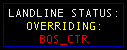
The controller you are overriding (BOS_CTR in this example) will see a button similar to the following if he is using VRC:
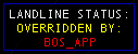
During this time, you can talk to BOS_CTR by pressing your PTT key, and he can respond just by talking. To end the override, type .rls, which is short for "release". Clicking the Landline Status button in your button bar will also end the override call, regardless of whether or not you initiated the call. Note that the controller being overridden can still talk to pilots on his frequency normally, using his PTT key.
Text Overrides
A Text Override is a way to send a special private chat message to another controller, so that the message will be highlighted in some way in order to get the controller's attention. Text overrides are normally used if you need to send a relatively urgent message to a controller who might otherwise be ignoring normal private messages, and is too busy for you to cut in with a voice override or intercom call.
You send a text override in the same way that you send any private message (See "Chat Windows") but you prefix the message with three asterisks.
In VRC, text overrides show up in both a private chat window and in the radio text area, and are accompanied by a sound. Here's an example:
![]()
You would send the above text override using a command similar to this:
.msg BOS_CTR *** Initiate holds for GDM3 arrivals ASAP
Or, if you already have a private chat window open with the controller, you can just type the message (starting with the asterisks) directly into the chat window command line, and it will be displayed as a text override if the controller is using VRC.
Intercom Calls
Intercom calls are similar to overrides, except in the case of an intercom call, both parties need to use their PTT key to talk. Neither side has an open mic, and neither side can talk to pilots during the call.
To initiate an intercom call to the controller with Sector ID 20, type .ic 20 and press Enter. You will see the following button appear in your Button Bar:
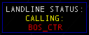
If another controller initiates an intercom call with you, his entry in the Controller List will be highlighted in red, and you will see see a button similar to the following:
Before the intercom call begins, you must first accept it by clicking on the button. The entry in the Controller List will turn green, and the button will change to show that you are now on an active intercom call:
To speak to the other controller during an intercom call, simply press your PTT key. If you need to talk to a pilot on your voice frequency while still on the intercom call, you can place the call on hold by typing .hold. The button will show that the call is on hold:
To resume the call, type .hold again. When you are ready to end the call, simply click on the Landline Status button or type .rls.
Monitoring
The last type of ground-to-ground voice call is called monitoring. When you are monitoring another controller, you simply hear all voice communications that they hear, including air-to-ground and ground-to-ground calls. The other controller cannot talk back to you directly. This is useful for an instructor to monitor a student.
When you are monitoring a controller, you will see a Landline Status button similar to the following:
If you are being monitored by another controller, that controller's entry in your Controller List will turn blue. Note that this is different from being overridden in that the controller who is monitoring you only hears your voice when you press your PTT key to talk to pilots or another controller via an override or intercom call. Your mic is not open while you are being monitored.
Use the .mon command to monitor a controller. For example, to initiate monitoring of the controller with Sector ID 20, type .mon 20 and press Enter.
To stop monitoring a controller, simply click on the Landline Status button or type .rls.
The Right-Click Menu
Most of the aircraft-specific functions covered in the previous few pages are also accessible via a pop-up menu, which can be displayed by right-clicking on a target or data tag. Here's a screenshot of the menu:
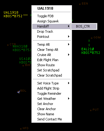
The options will change depending on certain conditions such as whether or not you are currently tracking the aircraft. For example, if you are tracking the aircraft, you will see a sub-menu listing all controllers in range to which you might hand off the aircraft. This list will not include GND or DEL facilities.
The Flight Strip Bay
In the real world, many controllers use flight progress strips to keep track of various bits of information pertaining to a particular flight. Different controllers in different regions use flight strips in very different ways, but the core concept is always the same: flight strips are used as a visual aid for the organization of your airspace and the efficient handling of aircraft.
VRC provides a simulated Flight Strip Bay in which you can store flight progress strips for some or all of the aircraft under your control. To see an example of what the VRC flight strip bay looks like, view this screenshot.
The VRC flight strip bay has a fixed width with either one or two columns. Use to the General Settings window to switch between the two sizes.
The following diagram details the purpose of each area on a single flight strip:
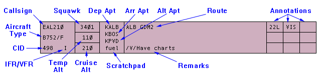
Creating Flight Strips
There are three ways to add a flight strip to your bay. The first is to hold the Alt key and slew the aircraft's target. The second way is to use the .strip key command. For example, to create a flight strip for EAL210, type .strip EAL210 and press Enter. Or, if EAL210 is already selected, you can simply type .strip then press Enter. The third way to create a strip is to hold the Alt key and click an aircraft in your Aircraft List. (See "The Aircraft List" for more information.)
When a strip is added to the bay, most of the data fields on the strip are automatically filled in by VRC, and it is automatically given an appropriate color based on your color selections. Different colors can be assigned for arrivals, departures, overflights, local traffic and VFR. See "Configuring the Scope" for details on configuring colors.
To view a pop-up menu with options for the selected flight strip, right-click anywhere on the strip.
Rearranging Flight Strips
VRC allows you to rearrange the strips in your Flight Strip Bay. This might be used by a Tower controller to order the strips based on the actual order the aircraft will be given takeoff clearance. To move a strip, simply click on it and drag it to a new location. As you move the strip, a blue line will be drawn in the strip bay at the point where the strip will be placed when you release the mouse button.
Copying Flight Strips
Note that you can have more than one strip for a given aircraft. One example of where this is useful is for enroute controllers who want to group the strips based on certain waypoints the aircraft will be overflying in order to give a clear picture of potential conflicts in those areas. To add another strip for an aircraft, follow the same procedure as for creating the initial strip, or hold the Shift key and click and drag the strip. This will cause a duplicate strip to appear, which you can then position anywhere in the strip bay.
Annotating Strips
The nine boxes at the far right end of the flight strip allow you to enter small bits of text, or annotations, onto the strip. A Tower controller might use this for indicating the runway that was assigned to a departure. An Approach controller might annotate a strip to show the approach type that an arrival requested.
To annotate a strip, click on one of the nine boxes. A small text box will appear into which you can type some text. Press Enter to accept your annotation and print it on the strip. Press Esc to cancel your annotation and revert to the previous text, if any.
Note that when pushing a flight strip to another controller, your annotations will only be retained and shown on the strip in the receiving controller's bay if the receiving controller is using VRC 1.2 or later.
Creating Separators
You can also add separator strips to the bay. A separator is a simple strip that has nothing but a text label printed on it. Separators are used to logically group your flight strips. For example, a Tower controller might have a separator for each active runway, and/or separators for arrivals, departures and local traffic. Here's an example of a separator:

To create a separator, type .sep followed by the name of the separator, then press Enter. For example, to create the separator shown in the example above, you would enter the following command: .sep Runway 22L Arrivals.
Note that you can rename a separator in the same way that you annotate strips. (See above.) Simply click on the separator text to display an edit box. Type the new separator text and press Enter. Press Esc to cancel the change.
Separators are stored in your profile and will automatically be added to the strip bay when you next load the profile.
Deleting Flight Strips
To delete any flight strip or separator, hold the Alt key and click the strip. You can delete all strips at once by entering the .nostrips command.
The Oceanic Tracks Window
VRC has the ability to download current oceanic tracks and plot them on your scope. As of version 1.2, only North Atlantic Tracks (NAT) are available.
To display oceanic tracks, press Ctrl-O. The following window will be shown:
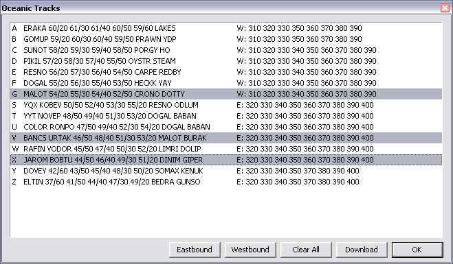
Initially, the list will be empty. Press the "Download" button to fetch the latest tracks from the VRC web server. To plot a track on your scope, simply click on the track entry in the list to select it. You can display some or all of the tracks, in any combination. You can display all of the eastbound or westbound tracks by pressing the appropriate button in the row of buttons across the bottom of the window.
Note that by default the VRC server retains tracks even if they are not considered active tracks for the current day. If you only want to see tracks that are active for today, check the appropriate box in the General Settings on the Miscellaneous tab.
Thanks go to Ian Elchitz of Simroutes.com fame for providing the raw data feed for this feature. Thanks also to Tobias Niederhasuer, who's Nat Tracker site is the original source of the data for Simroutes.com.
Conflict Alerts
Sometimes, despite your best efforts, two aircraft will get a bit too close and you'll lose minimum separation between them. This is called a conflict. VRC provides a number of options for determining when conflicts are detected and alerts are triggered. See "Configuring VRC" for details on these settings.
VRC allows you to set a minimum for both vertical and lateral separation between aircraft under your control. You can also specify an altitude floor below which conflicts will not be detected. This is useful if you are getting false conflict alerts from aircraft flying in the pattern at an airport within your airspace while working approach.
When a conflict is detected between two aircraft under your control, VRC sounds a looping conflict alert warning and optionally draws separation rings around the aircraft. The radius of these rings is equal to the lateral separation minimum you specify in the General Settings. Depending on the selected radar mode, you may also see a blinking "CA" notification above the datablock. Also, the datablock color will change to the color you have selected for aircraft in conflict. Here's a screenshot of a conflict:
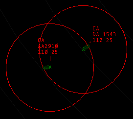
VRC will also add a button to the Button Bar indicating that there is a conflict detected. Here's a screenshot:

To silence the conflict alert sound, click the above button, press CTRL+S or type .silence. The conflict will still be displayed on the scope, but the looping conflict alert sound will stop.
Any conflict in progress will continue to be displayed until the conflict is resolved. VRC calculates the flight path of the two aircraft and cancels the conflict alert if it determines that separation is increasing. As long as the separation remains below minimums and is either remaining constant or decreasing, the conflict alert will continue to be displayed.
Note that aircraft not being tracked by you can still cause a conflict, but you will only see the separation rings and hear the conflict sound if you are tracking one or both of the conflicting aircraft.
The Virtual Tower View
With the release of version 1.1, VRC now includes a Virtual Tower View. The tower view allows you to connect Microsoft Flight Simulator 2004 (FS9) to VRC in order to see all aircraft in the airport area within the simulator. When you activate the tower view, VRC creates a multiplayer session and adds aircraft to it. All aircraft within 15 NM of your primary visibility center are added to the session. You can then connect FS9 to the session in order to see the aircraft. FS9 can be running either on the same computer as VRC, or on a different computer on the network.
To activate the tower view, choose "Start MP Session" from the File menu. You will see a message indicating that VRC is creating the multiplayer session. After a short pause, you will see a Success message. All VRC program activity is suspended during these few seconds, so it's a good idea to start the MP session before actually connecting to VATSIM and working with traffic. Once you see the success message, you should be able to connect FS9 to the MP session.
As stated above, VRC only adds aircraft to the multiplayer session if they are within 15 NM of your primary visibility center, so the first thing you should do after starting the MP session is to fix your visibility center at your airport. For example, if I'm working the Boston tower, the first thing I'll do is issue the .vis KBOS command. Then I'm free to pan my scope around without worrying about aircraft dropping out of the multiplayer session.
This is especially important for CTR or APP controllers who are also providing tower services at one field in their sector. For example, if I'm on BOS_CTR, I might have a 400 NM range, and my scope may not be centered anywhere near KBOS, so if I want to use the tower view at KBOS, I must set my primary visibility center at KBOS.
Note that VRC just creates the multiplayer session and fills it with the aircraft that you see on your scope. It's up to you to configure FS9 with an appropriate viewpoint of the airport. A good way to do this is to modify the aircraft.cfg file for an aircraft that you never fly, such as the default C182 or C172. Within that file you'll find a setting called eyepoint. Set the last value on that line to an appropriate height for your tower. For example:
eyepoint= -3.95, -0.85, 370.0
This would set the pilot viewpoint to 370 feet above the ground.
There are two other sections of the aircraft.cfg file that you'll need to modify, in order to get your viewpoint to remain "flat" as you pan around. The first is the static_pitch value. It needs to be set to zero, like so:
static_pitch=0.0
The other area you need to modify is the first line of the [contact_points] section. For the C182, it should be changed like so:
point.0 = 1, 0.48, 0.00, -3.33, 1500, 0, 0.5, 22.0, 0.3, 2.5, 0.7, 0.0, 0.0, 0
This is basically telling FS9 that the aircraft sits perfectly level on its tricycle gear, instead of resting with a slightly nose-high attitude. The reason this is important is because if you left the default values, the horizon would tilt slightly when you pan your view around in the virtual cockpit.
Now you can load up this aircraft, move to the airport where you will be controlling, and slew the aircraft into position at the tower. You may need to turn off collision detection in order to avoid having FS9 detect a building crash when you come out of slew mode.
Once you connect FS9 to the multiplayer session created by VRC, you should see the aircraft within FS9 when you are in the virtual cockpit view. You can use any normal means available for moving your viewpoint around. Active Camera provides a nice way to use the mouse to pan and zoom your view.
Note that in order for the tower view to work properly, you must have installed the model data when installing VRC. This option is enabled by default when you run the installer. You must also have the modelsets installed. You will already have the modelsets installed if you have Squawkbox 3 installed. If not, there is a separate installer available on the VRC downloads page.
The multiplayer session will remain active as long as VRC is running, even if you switch profiles. If you close VRC and restart it, you will also need to restart the multiplayer session.
See the screenshots page for some examples of what the Virtual Tower View looks like in action.
Some Useful Tools
The Ruler
When controlling aircraft, there are two pieces of information which you need to use very often. The first is an aircraft's heading to a particular point. The other is the distance between an aircraft and another aircraft or point. To make it easier for you to determine these pieces of information, VRC provides the Ruler tool. This tool allows you to draw a line from one point on the scope (usually an aircraft) to another, and measure the heading between the two points as well as the distance.
To use the Ruler, double-click on any point on the scope, hold the left mouse button down, and drag the mouse. A line will be drawn from the double-click point to the mouse cursor, updated as you move the mouse. A box will be drawn showing the heading, reciprocal heading, and distance between the two points. Here's an example:
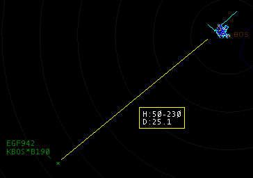
The line will be cleared when you release the mouse button, but the last-displayed data will be shown in a button on the Button Bar for your reference. Here's an example:

Separation Predictor
The Separation Predictor tool allows you to predict the flight paths of two aircraft and determine at what point the two aircraft will converge on each other. This is best illustrated with a screenshot:
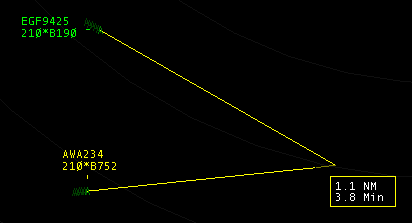
In this screenshot, the two aircraft are converging, and VRC has predicted that they will pass closest to each other at the point shown by the end of the two vector lines. At that point, they will have 1.1 NM of lateral separation. It will take 3.8 minutes for the aircraft to arrive at that point given their current ground speed.
To activate the Separation Predictor lines for two aircraft, first select one of them as normal. (See "Selecting Aircraft" for details.) Then, hold the Shift key and click the other aircraft. If VRC determines that the aircraft are on a converging course, the lines will be drawn and updated as the aircraft move. The lines will be erased after about 10 seconds.
Note that vertical separation is not taken into account when determining if the two aircraft are converging. Only their lateral separation is calculated.
Separation Links
Separation links are lines drawn between selected targets in order to show the lateral separation between the aircraft. The displayed distance is updated as the aircraft targets move. This feature is useful for showing the separation between aircraft when you have several targets in a line all on the same route, headed for the same approach, or on a localizer. Here's an example:
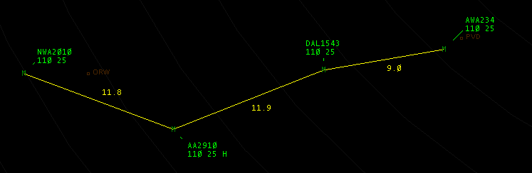
To create a separation link, radio-select the first aircraft, then hold the Shift and Alt keys, and click the second aircraft. The separation link will appear, and the second aircraft will be radio-selected. This allows you to Shift-Alt-Click several aircraft in a row and quickly create a chain of linked aircraft.
To remove a separation link, simply repeat the procedure. You can remove all separation links on a scope with the .noseplinks command.
Anchors
An anchor is a measurement of an aircraft's distance, heading and time to a particular airport, navaid or fixed point on the scope. Anchors are similar to the Ruler line tool, but they persist on the scope, are automatically updated as the aircraft moves, and must be manually cleared. There can only be one anchor per aircraft.
When you set an anchor, the calculated heading, distance and time for the anchor is shown below the aircraft's datablock. Optionally, a line is drawn from the aircraft to the point where it is anchored. Here's a screenshot:
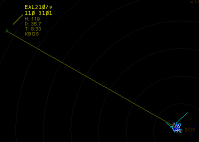
To set an anchor, make sure you have the aircraft selected, then type .an FIX followed by the ASEL key. For example, to anchor an aircraft on KBOS, type .an KBOS followed by ASEL. In this case, the text "KBOS" will be shown along with the anchor data, as in the screenshot above.
Another way to set an anchor is with the mouse shortcut. With the aircraft selected, hold the Shift key and right-click on the spot where you wish to anchor the aircraft.
To clear an anchor, either type .an followed by ASEL (with the aircraft selected) or type .noanchors which will clear all anchors for all aircraft.
Sticky Notes
VRC 1.2 introduces a new feature called Sticky Notes. A sticky note is an arbitrary string of text that you can place anywhere on the scope, to serve as a reminder of some piece of information. Examples include coordination specifics between yourself and an adjacent controller, a requested approach at a satellite field, information about special use airspace activity, etc. Here's what sticky notes look like:
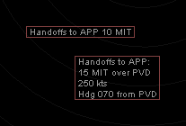
To create a sticky note, enter .sticky followed by the text of the sticky note, then press Enter. To create a multi-line sticky note, separate the lines with pipe characters. To create the multiline sticky note shown in the example above, you would use the following command:
.sticky Handoffs to APP:|15 MIT over PVD|250 kts|Hdg 070 from PVD
After pressing enter, the sticky note will appear at the center of your screen. You can then click and drag the note to a new location.
Also, instead of pressing enter, you can just type in the .sticky command then click on the screen at the location where you want the note to appear.
In order to delete or edit a sticky note, right click on the note and choose the appropriate option from the menu. If editing the note, a small text box will appear where you can make changes to the note. Press Enter to save your changes.
Separation Rings
VRC allows you to draw separation rings around the aircraft you are tracking. This allows you to quickly see whether or not you are risking losing lateral separation between two aircraft. The radius of these rings is defined in the General Settings as the lateral separation minimum for conflict detection. To toggle the separation rings, press CTRL+R. Here's a screenshot:
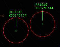
Note that separation rings are only drawn for aircraft you are tracking.
The Timer Button
By default, the Button Bar includes a Timer Button. This button has two clickable areas which you can use to start either a two or three-minute countdown timer. This is useful for ensuring the proper amount of wake turbulence separation between successive departures, for example. Here's a screenshot:

To start the countdown, simply click within the appropriate box. The timer button will then show the time remaining in a large yellow font, as shown here:

When the countdown reaches zero, a notification is displayed in the radio history area and the reminder sound is played. You can cancel the timer during the countdown by clicking the button. You can hide the timer button using the checkbox in the General Settings.
Text Traffic Advisories
VRC provides a tool for quickly sending a traffic advisory to text-only pilots. To do this, select the aircraft you wish to send the advisory to, then hold the CTRL+SHIFT keys, and click the aircraft you wish to point out. Text similar to the following will be transmitted to the selected aircraft:
DAL1543, traffic six o'clock and 10 miles, east bound, a B744 at 11000.
If both aircraft are on the ground (travelling less than 50 knots) then a "give way" command will be sent, similar to the following:
DAL1432, give way to the A320 at your three o'clock.
The Reminder List
During a controlling session, you will often get requests from pilots but not be able to handle them right away. When you're busy, it's easy to forget about these requests and leave the pilot hanging. To help with this problem, VRC provides the Reminder List. When aircraft are on your Reminder List, every 30 seconds, a sound is played and a message is displayed in your radio text area. The Aircraft List also shows each aircraft along with the amount of time that aircraft has been on your reminder list. The list is sorted based on how long the aircraft have been on your reminder list, starting with those that have been on it the longest.
To add an aircraft to your Reminder List, first select the aircraft, then press the ASEL key while there is nothing entered on the command line. Repeat this procedure to remove an aircraft from your Reminder List.
Note that the 30 second reminder can be disabled in the General Settings if you find it obtrusive. With the sound and message disabled, you will need to rely on the Aircraft List to keep track of which aircraft are on your Reminder List.
Performing a Mass Handoff
At the end of a controlling session, if another controller is signing on to take your place, you can hand off all of the aircraft that you are currently tracking to the new controller by performing a mass handoff. To do this, type .transfer followed by the new controller's sector ID, followed by the Enter key. VRC will initiate a handoff for each of your tracked aircraft to the new controller.
Displaying an aircraft's route (Shift-F6)
To get a quick graphical view of an aircraft's filed route, hold the CTRL+ALT keys and click the aircraft's target. This will draw a line on the scope between each waypoint on the pilot's filed route, as long as those waypoints are defined in your currently-loaded sector file. Here's an example:
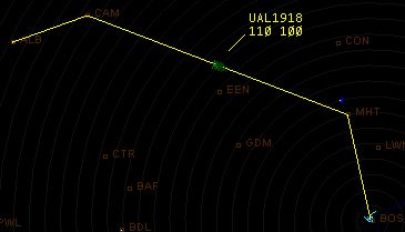
The line will remain on the screen for about five seconds.
Looking Up Aircraft Information
By issuing the .acinfo command, followed by selecting an aircraft, you can look up some useful information about the selected aircraft type. The information retrieved includes the following:
- ICAO type code
- Manufacturer name
- Model name
- Engine type and number of engines
- Wake turbulence class (Small/Medium/Large/Heavy)
- Climb/descent rates
- Same Runway Separation (SRS) category
The response is shown in the radio history area on your primary scope. Here's an example response:
Aircraft info for AA2910: B744 - BOEING COMPANY (USA) 747-400 (International, winglets) - Engines/Class: 4J/H - C/D Rates: 3000/3000 - SRS Category III
This data comes from a file downloaded from the VRC web site containing the data found in the FAA 7110.65 document, appendix A. When VRC first starts, it checks for updates to this data file, so you will always have the latest version.
Requesting Relief
If you are planning to end your controlling session soon, you should let the other controllers know so that they can offer to relieve you if possible. To do this, type .break and press Enter. This will cause your callsign to show in pink in other controller's Controller Lists. Your callsign will show as pink also in your button bar. To cancel the relief request, enter the .nobreak command.
Requesting help
VRC provides a way for you to request urgent help from all controllers within range. To do this, type .help followed by a message, followed by the Enter key. For example: .help I'm going down the tubes! Need relief! This will cause your callsign to change color on the Controller List for any controllers within range. In ASRC, your callsign will flash between pink and red. In VRC, your callsign will be shown in orange. On your scope, your callsign will be shown in orange in the Button Bar.
If you see someone requesting help in this manner, you can view their help request message by clicking their callsign in your Controller List. The help message will be shown along with the other controller info in the box at the bottom of the Controller List.
To cancel your help request, simply type .nohelp followed by Enter.
Summoning a Supervisor
If you need the assistance of a VATSIM supervisor, such as to deal with a non-responsive pilot, you can use the .wallop command. For example: .wallop Need a sup near KBOS, non-responsive pilot buzzing the tower. This will send your message to all supervisors on the network. If a supervisor is available, he or she will contact you via private message.
Text Overrides
A Text Override is a way to send a special private chat message to another controller, so that the message will be highlighted in some way in order to get the controller's attention. Text overrides are normally used if you need to send a relatively urgent message to a controller who might otherwise be ignoring normal private messages, and is too busy for you to cut in with a voice override or intercom call.
You send a text override in the same way that you send any private message (See "Chat Windows") but you prefix the message with three asterisks.
In VRC, text overrides show up in both a private chat window and in the radio text area, and are accompanied by a sound. Here's an example:
![]()
You would send the above text override using a command similar to this:
.msg BOS_CTR *** Initiate holds for GDM3 arrivals ASAP
Or, if you already have a private chat window open with the controller, you can just type the message (starting with the asterisks) directly into the chat window command line, and it will be displayed as a text override if the controller is using VRC.
Viewing Mouse Coordinates
If you wish to see the latitude and longitude of the mouse cursor as you move the mouse over the scope, you can enable the Mouse Location option on the View menu. The mouse location coordinates can be displayed either in Degrees/Minutes/Seconds format, or in decimal degrees format. The display format is determined by a checkbox in the General Settings window, on the Miscellaneous tab.
Session Statistics
During your controlling session, VRC keeps track of a number of different statistics. They include:
- How long you have been connected to the network
- The number of aircraft that have appeared on your scope
- The number of aircraft you have tracked
- The number of flight plans you have amended
- The number of handoffs you have initiated
- The number of handoffs you have received
- The number of handoffs you have refused
- The number of squawk codes you have assigned
- The number of cruise altitudes you have assigned or amended
- The number of temporary altitudes you have assigned
- The number of scratchpad modifications you have made
- The number of conflicts that have been detected on your scope
To view these statistics, enter the .showstats command. You will see the data shown in your radio message area. You may need to expand the size of your radio message area or press the Page Up and Page Down keys to see all of the stats.
To reset these statistics to zero, enter the .resetstats command.
Advanced Topics
Realistic Data Tags Mode
With the Realistic Data Tags Mode enabled (see the Data Tags tab on the General Settings window) you can only tag-up or click to select aircraft which are squawking their assigned code. This more closely mimics real-world systems which rely on the pilot squawking the correct code in order to associate the target with information in the computer such as callsign and flight plan.
Note that even in Realistic tags mode, you can still click on aircraft to send the "Please contact me ..." message using the HOME key. You can also still use the ASEL key to select an aircraft and interact with it, such as assigning a squawk, editing the flight plan, etc.
Custom Server List
If you need to add servers to the list downloaded from VATSIM, you can create a custom servers file. This file is called myservers.txt and should be kept in your "My Documents\VRC" folder. Each line of this file represents a single custom server. The line must contain the server IP address or hostname, followed by a space, followed by a descriptive name for the server. The name will show up in the server list in the Connect window. Here's an example entry:
sweatbox.vatsim.net Public Sweatbox
The Debug Window
In order to show some basic debugging information on the scope, type .debug 1 followed by the Enter key. This will show a debug information box similar to the following on each display:
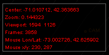
To turn off the debug window, issue the .debug 1 command again.
Anti-Aliasing
If the lines and text on your screen look somewhat blurry, you may have anti-aliasing turned on. Here's an example of what this looks like:
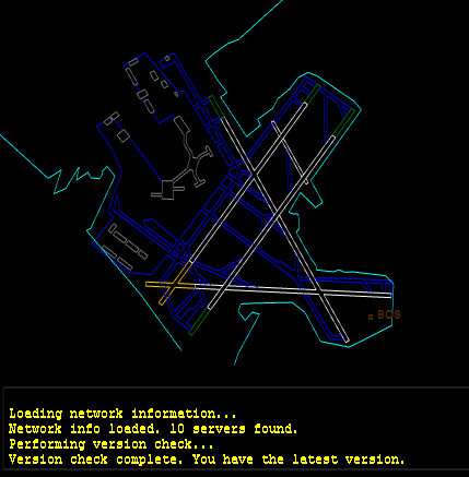
Refer to your video card manual to learn how to disable anti-aliasing.
Appendix A - Command Reference
[ Function Key Commands | Miscellaneous Key Commands | Dot Commands | Mouse Shortcuts ]
| |||||||||||||||||||||||||||||||||||||||||||||||||||||||||||||||||||||||||||||||||
| ||||||||||||||||||||||||||||||||||||||||||||||||||||||||||||||||||||||||||||||||||||||||||||||||||||||||||||
| ||||||||||||||||||||||||||||||||||||||||||||||||||||||||||||||||||||||||||||||||||||||||||||||||||||||||||||||||||||||||||||||||||||||||||||||||||||||||||||||||||||||||||||||||||||||||||||||||||||||||||||||||||||||||||||||||||||||||||||||||||||||||||||||||||||||||||||||||||||||||||
| |||||||||||||||||||||||||||||||||||||||||||||||||||||||||||||||||||||||||||
Appendix B - Files in the VRC Folder
After your first session with VRC, your installation folder will contain some or all of the files listed below. As of VRC 1.2.4, some of these files are stored in your "My Documents\VRC" folder.
|
Appendix C - Contents of a Profile
All of your profiles and their individual settings are stored in the VRC.ini file which is installed in the main installation directory you chose when installing VRC. Following is a summary of the data included in a profile:
- All options found on the General Settings window.
- The last-used ATISMaker template, ICAO code and runway list.
- All color selections.
- All sound assignments and whether or not sounds are active.
- Current audio device selections and volume levels.
- The last microphone calibration results.
- The size and position of all tool windows.
- Any separators placed in the Flight Strip Bay.
- Bookmarks for the Primary Display.
- All defined entries in the Comms Panel.
- All fields from the Connect Window. (Callsign, rating, etc.)
- The size (in lines) of the radio history area.
- All weather stations being monitored in the weather panel.
For each Display Window, the following items are stored:
- The currently-loaded sector file.
- The selected radar mode.
- All toggles on the View menu.
- All visible diagrams.
- The size and position on the screen.
- The center point of the scope.
- The zoom level of the scope.
- The center point for the range rings.
The following items are not stored in the profile:
- The location and size of chat windows. (These are stored globally in the Windows Registry.)
- Configured visibility centers.
Appendix D - Error Messages
Following is a list of the various error messages you may encounter while working with VRC. Refer to this list for a description of the error if it is not clear from the context.
- Aircraft not found.
- You have attempted to perform an action on an aircraft and you specified an unknown callsign.
- All squawk codes in the configured range are taken.
- You have attempted to assign a squawk code to an aircraft but all codes in the range specified in your POF file are in use by other aircraft.
- Already monitoring the maximum number of weather stations.
- You have attempted to add a weather station to the weather panel, but you are already monitoring the maximum of 20 stations.
- Amendment command not supported. Please use flight strip window.
- You attempted to use a flight plan amendment command from ASRC that is not supported in VRC.
- ATIS contains too many lines!
- Your ATIS text contains too many lines. The recommended number of lines is 4. The absolute maximum allowed by VRC is 10.
- ATIS is currently empty.
- You have requested your own ATIS, but it is empty.
- Callsign in use
- You have attempted to connect with a callsign that another controller is already using.
- Callsign invalid
- The callsign you specified in the Connect window was rejected by the server as invalid.
- CID/PID was suspended
- Your VATSIM account has been suspended.
- Command restricted to supervisors and admins.
- You attempted to use a command for which you do not have the appropriate privileges.
- Connection failed.
- Your connection to VATSIM has failed.
- Controller not found.
- You attempted to perform a command on a controller using an unknown callsign.
- Could not accept land line call.
- There was a problem making the requested ground-to-ground voice connection.
- Could not find point: _____.
- You attempted to locate or use a fix, navaid or airport that was not found in the sector file.
- Could not open land line.
- There was a problem making the requested ground-to-ground voice connection.
- Could not write to server list cache file.
- VRC was unable to write the servers.txt file which stores the downloaded server list. This could be a file permissions problem.
- Error loading alias file!
- Your specified alias file could not be found or opened.
- Error loading position file!
- Your specified POF file could not be found or opened.
- Error saving chat log to specified file.
- You attempted to save a chat window log to a file but the file could not be opened. This could be a file permissions problem.
- Error saving radio log to specified file.
- You attempted to save your radio text log to a file but the file could not be opened. This could be a file permissions problem.
- Fix, airport or navaid not found.
- You attempted to locate or use a fix, navaid or airport that was not found in the sector file.
- Flight strip not found for specified callsign.
- You attempted to delete a flight strip from the Flight Strip Bay, but no such strip existed in the bay.
- Handoff of _____ refused.
- You attempted to transfer control of the specified aircraft to another controller, but that controller refused the handoff.
- Invalid CID/password
- You attempted to connect to VATSIM with an invalid CID or incorrect pasword.
- Invalid control.
- You attempted to perform an action (such as initiating track) on an aircraft, yet you are not a valid controller. (Usually because you are an observer.)
- Invalid parameter. Enter either the sectorID or single-digit chat group index.
- You attempted to use the Controller Select (CSEL) key to open a chat window, but the specified sector ID or chat group index was not found in the Controller List.
- Invalid position for rating
- You attempted to connect to VATSIM and specified a facility for which you must have a higher rating.
- Invalid profile name.
- You attempted to save a profile and specified an invalid name. Profile names must consist of only letters, numbers, underscores and spaces.
- Invalid speed and/or heading detected on one of the selected targets.
- You attempted to activate the separation predictor lines for two aircraft, but one of those aircraft is reporting an invalid speed and/or heading.
- Invalid squawk code range.
- The range of squawk codes specified in the POF file is invalid. This could be caused by having the low end of the range set higher than the high end.
- Must click a different aircraft than the one that is radio selected.
- You attempted to send a traffic advisory to a pilot, but didn't select a different aircraft to point out. (You attempted to point out an aircraft to itself.)
- Must specify a callsign or use <ASEL>.
- You attempted to perform a command that requires a callsign parameter but didn't specify one.
- Must specify a single callsign.
- You attempted to perform a command that requires a single callsign parameter but didn't specify one or you specified too many.
- Must specify at least one separator label.
- You attempted to add a separator to the Flight Strip Bay but didn't specify the separator label.
- Must specify callsign.
- You attempted to perform a command that requires a callsign parameter but didn't specify one.
- Must specify filename as a single parameter.
- You attempted to save a chat or radio text log to a file but didn't specify the filename to use.
- Must specify URL.
- You attempted to open a web page via the .openurl command but didn't specify the URL.
- No aircraft selected.
- You attempted to send a traffic advisory to a pilot, but didn't have an aircraft selected.
- No departure airport filed.
- You attempted to request the METAR for an aircraft's departure airport, but the aircraft has no departure airport filed.
- No destination airport filed.
- You attempted to request the METAR for an aircraft's destination airport, but the aircraft has no destination airport filed.
- No flight plan selected.
- You attempted to amend an aircraft's route with the .am command, but had no flight plan loaded into the Flight Plan Editor window.
- No flightplan
- You requested the flight plan for an aircraft which has not yet filed one.
- No frequency specified.
- You attempted to use an entry in the Comms Panel for which no frequency is defined.
- No history to save!
- You attempted to save the history for a chat window or the radio text history but there has been no chat or text radio messages recieved yet.
- No more clients
- The server you attempted to connect to is full.
- No such callsign
- This generic error comes from the server when you attempt to perform an action on a callsign that does not exist on the network.
- No such weather profile
- You requested the weather for a station for which the server has no weather information.
- No voice channel specified.
- You attempted to connect to the voice channel associated with a Comms Panel entry, but no voice channel has yet been defined for the selected entry.
- Not authorized software
- You are not authorized to use VRC on the selected server, or a network timing problem has occurred and you have been disconnected.
- Not connected.
- You have attempted some function which requires you to be connected, while not connected.
- Not enough parameters.
- The command you attempted to perform requires additional parameters.
- Not valid control
- You attempted to perform an action (such as initiating track) on an aircraft, yet you are not a valid controller. (Usually because you are an observer.)
- Not your control.
- You attempted to perform an action on an aircraft that requires you to be tracking the aircraft, but another controller currently has track.
- Observers cannot initiate land line calls.
- Self-explanatory.
- Observers cannot send text radio messages.
- Self-explanatory.
- Point not found.
- You attempted to locate or use a fix, navaid or airport that was not found in the sector file.
- Requested level too high
- You attempted to connect to VATSIM and specified a rating for which your CID does not qualify. Choose a lower rating.
- Specified display does not exist.
- You attempted to send a command to a secondary display which does not exist.
- Specify two points or one point and select an aircraft.
- You attempted to use the .rsb command and did not specify enough parameters.
- Targets not converging.
- You attempted to activate the separation predictor lines on two aircraft which are not on converging courses.
- Targets will not converge within one hour.
- You attempted to activate the separation predictor lines on two aircraft which will not converge within a reasonable amount of time.
- Unknown controller list index.
- You attempted to open a chat window using a one or two character index from the Controller List, but the specified index does not exist.
- Version check failed! HTTP error.
- VRC's initial version check failed. This is not a problem unless it happens consistently. In that case, check your firewall to be sure web connections to vrc.rosscarlson.dev are not blocked.
- You can only monitor one controller at a time.
- Self-explanatory.
- You must select two different aircraft.
- You attempted to activate the separation predictor lines without selecting two distinct aircraft.
- You were forcibly disconnected from the network. Reason: __________
- You were disconnected from the network, most likely by a supervisor or administrator. Refer to the specified reason.
- Could not open UDP voice port. Perhaps another VATSIM program is running such as ASRC?
- VRC could not open the network port needed for voice connections. This is usually because it is already in use by another program such as ASRC, AVC, etc.
- Could not read and/or parse VRC.ini
- VRC could not find the VRC.ini file, or did not have permissions to read it. The VRC.ini file must be in your "My Documents\VRC" folder.
- Error loading POF file!
- VRC could not locate or read the POF file specified in the profile you are trying to load. Make sure the file exists in the specified location and that VRC has the appropriate file permissions to read it.
- Error loading alias file!
- VRC could not locate or read the alias file specified in the profile you are trying to load. Make sure the file exists in the specified location and that VRC has the appropriate file permissions to read it.
- The default profile cannot be deleted.
- VRC does not let you delete the Default profile so that you can always revert to it in case something in your profile settings gets corrupted.
- Are you sure you want to delete the selected profile? This action cannot be undone.
- This is just a reminder that if you delete a profile, it is gone for good. There is no way to restore it from the Recycle Bin or undo the deletion.
- Invalid ICAO code. Must be 4 characters.
- You attempted to enter an airport code into ATISMaker, but did not specify a 4-character code as required.
- Invalid runway.
- Runways entered into ATISMaker must be one or two digits, followed by an optional C, L, or R for Center, Left, or Right.
- Invalid airport code.
- You attempted to enter an airport code into the Arrival or Departure Fields lists, but did not specify a 4-character code as required.
- Could not retrieve server list from network. Using the cached server list and user-defined servers.
- VRC tried to download the VATSIM server list from the network, but the connection failed. This is often due to a firewall or antivirus running on your computer. You can usually still connect to VATSIM using the cached server list.
- You cannot overwrite the default profile. Please choose another name.
- VRC does not let you overwrite the Default profile so that you can always revert to it in case something in your profile settings gets corrupted.
- Must be an active controller to initiate ground-to-ground calls.
- You attempted to initiate a ground-to-ground call while logged in as an observer.
Appendix E - The VRC End-User License Agreement
END USER LICENSE AGREEMENT FOR Virtual Radar Client (VRC) SOFTWARE
IMPORTANT-READ CAREFULLY: This End-User License Agreement ("EULA") is a legal agreement between you (either an individual person or a single legal entity, hereinafter referred to in this EULA as "You") and Ross A. Carlson (hereinafter referred to as the "Developer") for the Virtual Radar Client (VRC) including any associated media, printed materials and electronic documentation (the "Software Product"). The Software Product also includes any software updates, add-on components, web services and/or initial supplements that the Developer may provide to you or make available to you after the date you obtain your initial copy of the Software Product to the extent that such items are not accompanied by a separate license agreement or terms of use. By installing, copying, downloading, accessing or otherwise using the Software Product, you agree to be bound by the terms of this EULA. If you do not agree to the terms of this EULA, do not install, access or use the Software Product. Instead, you should delete it immediately.
SOFTWARE PRODUCT LICENSE
The Software Product is protected by intellectual property laws and treaties. The Software Product is licensed, not sold.
1. GRANT OF LICENSE.
This Section of the EULA describes your general rights to install and use the Software Product. The license rights described in the Section are subject to all other terms and conditions of this EULA.
General License Grant to Install and Use Software Product. You may install and use the Software Product on a computer, device, workstation, terminal or other digital electronic or analog device ("Device"). This license is granted exclusively to you for the Software Product described within and may not be shared or transferred under any circumstances.
Reservation of Rights. All rights not expressly granted are reserved by Developer.
2. DESCRIPTION OF OTHER RIGHTS AND LIMITATIONS.
Copy Protection. The Software Product may include copy protection technology to prevent the unauthorized copying of the Software Product or may require original media for use of the Software Product on the Device. It is illegal to make unauthorized copies of the Software Product or to circumvent any copy protection technology included in the Software Product.
Limitations on Reverse Engineering, Decompilation, and Disassembly. You may not reverse engineer, decompile or disassemble the Software Product, except and only to the extent that such activity is expressly permitted by applicable law notwithstanding this limitation.
Limitations on Modification of Software Product. You may not modify the Software Product in whole or part in any way without the express prior written approval of the Developer. This includes, but is not limited to, the modification of any installation routines, packaging and/or program display elements (such as multiplayer aircraft) from the original state of the Software Product as provided to you by the Developer.
Limitations on Redistribution of Software Product. You may not redistribute the Software Product in whole or part in any way without the express prior written approval of the Developer.
Trademarks. This EULA does not grant you any rights in connection with any trademarks or service marks of the Developer.
No rental, leasing or commercial hosting. You may not rent, lease, lend or provide commercial hosting services to third parties with the Software Product.
Agreement to Transfer of Data by Software Product. By installing, copying, downloading, accessing or otherwise using the Software Product, you hereby grant permission to the transmission of certain data from your local Device to a host networks server hardware for use in online flight simulation. The data transmitted to a host networks server hardware shall be limited to various data and information from your flight simulator software program including, but not limited to, aircraft performance and location data generated by said simulator program. In addition, you further agree to the transfer of your hard disk drive volume ID from your primary system drive, the version number of the Software Product and the callsign currently loaded into the Software Product to the Developer each time you startup the Software Product. No information other than data generated by your flight simulation software and the data expressly set forth herein which would personally identify you shall be subject to the terms of this paragraph. However, the terms of this paragraph expressly exclude any information you provide via the Software Product for purposes of logging onto a particular host network. The provision of any such information shall be governed by the terms and conditions of your membership with such host network.
Support Services. The Developer may, in his sole discretion, provide you with support services related to the Software Product ("Support Services"). Use of Support Services is governed by the Developers policies and programs described in the user manual, in "online" documentation, or in other Developer-provided materials. Any supplemental software code provided to you as part of the Support Services shall be considered part of the Software Product and shall be subject to the terms and conditions of this EULA. You acknowledge and agree that the Developer may use technical information you provide as part of the Support Services for his business purposes, including for product support and development. The Developer will not utilize such technical information in a form that personally identifies you.
Software Transfer. Except as specified in this section, you may make a one-time permanent transfer of the EULA and Software Product directly and only to an end user. This transfer must include all of the Software Product (including all component parts, the media and printed materials, any upgrades, and this EULA). Such transfer may not be by way of consignment or any other indirect transfer. The transferee of such one-time transfer must agree to comply with the terms of this EULA, including the obligation not to further transfer this EULA and Software Product. Subscription Products, if any are provided or otherwise made available, are non-transferable.
Termination. Without prejudice to any other rights, the Developer may, in his sole discretion, terminate this EULA if you fail to comply with the terms and conditions herein. In such event, you must immediately destroy all copies of the Software Product and all of its component parts.
3. UPGRADES.
If the Software Product is labeled as an upgrade, you must be properly licensed to use a product identified by the Developer as being eligible for the upgrade in order to use the Software Product. A Software Product labeled as an upgrade replaces or supplements (and may disable) the product that formed the basis for your eligibility for the upgrade. You may use the resulting upgraded product only in accordance with the terms of this EULA. If the Software Product is an upgrade of a component of a package of software programs that you licensed as a single product, the Software Product may be used only as part of that single product package and may not be separated for use on more than one Device.
The Software Product may offer automatic and/or user optional downloadable upgrades. If you agree to any such upgrades, then data files will be downloaded which will replace the Software Products originally installed data files. Any such upgrades will be for data files only and will not include any executable files.
4. INTELLECTUAL PROPERTY RIGHTS.
All title and intellectual property rights in and to the Software Product (including but not limited to any images, photographs, animations, video, audio, music, text, and "applets" incorporated into the Software Product), the accompanying printed materials and any copies of the Software Product are owned by the Developer or his suppliers. All title and intellectual property rights in and to the content that is not contained in the Software Product, but may be accessed through use of the Software Product, is the property of the respective content owners and may be protected by applicable copyright or other intellectual property laws and treaties. This EULA grants you no rights to use such content. If this Software Product contains documentation that is provided only in electronic form, you may print one copy of such electronic documentation. You may not copy the printed materials accompanying the Software Product for any other purpose including, but not limited to, redistribution without the express prior written consent of the Developer.
5. BACKUP COPY.
After installation of one copy of the Software Product pursuant to this EULA, you may keep the original media on which the Software Product was provided by the Developer solely for backup or archival purposes. If the original media is required to use the Software Product on the Device, you may make one copy of the Software Product solely for backup or archival purposes. Except as expressly provided in this EULA, you may not otherwise make copies of the Software Product or the printed materials accompanying the Software Product.
6. APPLICABLE LAW.
If you exercise this license in the United States, then this EULA is to be construed in accordance with the laws of the United States and the State of Vermont. If you exercise the license of this Software Product in any other country, then local law applies.
Should you have any questions concerning this EULA, please send e-mail to ross@carlson.info.
7. WARRANTY.
THIS SOFTWARE PRODUCT IS NOT COVERED BY ANY WARRANTY OR CONDITION, EXPRESS, IMPLIED OR STATUTORY. THERE IS NO WARRANTY OR CONDITION OF ANY KIND.
Any supplements or updates to the SOFTWARE PRODUCT, including without limitation, any (if any) service packs or hot fixes provided to you are not covered by any warranty or condition, express, implied or statutory.
8. DISCLAIMER OF WARRANTIES.
THIS SOFTWARE PRODUCT IS NOT COVERED BY ANY WARRANTY OR CONDITION, EXPRESS, IMPLIED OR STATUTORY. THIS SOFTWARE PRODUCT IS NOT COVERED BY ANY OTHER EXPRESS WARRANTIES (IF ANY) CREATED BY ANY DOCUMENTATION OR PACKAGING. TO THE MAXIMUM EXTENT PERMITTED BY APPLICABLE LAW, DEVELOPER AND HIS SUPPLIERS PROVIDE THE SOFTWARE AND SUPPORT SERVICES (IF ANY) AS IS AND WITH ALL FAULTS, AND HEREBY DISCLAIM ALL WARRANTIES AND CONDITIONS, EITHER EXPRESS, IMPLIED OR STATUTORY, INCLUDING, BUT NOT LIMITED TO, ANY (IF ANY) IMPLIED WARRANTIES, DUTIES OR CONDITIONS OF MERCHANTABILITY, OF FITNESS FOR A PARTICULAR PURPOSE, OF ACCURACY OR COMPLETENESS OR RESPONSES, OF RESULTS, OF WORKMANLIKE EFFORT, OF LACK OF VIRUSES AND OF LACK OF NEGLIGENCE, ALL WITH REGARD TO THE SOFTWARE, AND THE PROVISION OF OR FAILURE TO PROVIDE SUPPORT SERVICES. ALSO, THERE IS NO WARRANTY OR CONDITION OF TITLE, QUIET ENJOYMENT, QUIET POSSESSION, CORRESPONDENCE TO DESCRIPTION OR NON-INFRINGEMENT WITH REGARD TO THE SOFTWARE.
9. EXCLUSION OF INCIDENTAL, CONSEQUENTIAL AND CERTAIN OTHER DAMAGES.
TO THE MAXIMUM EXTENT PERMITTED BY APPLICABLE LAW, IN NO EVENT SHALL DEVELOPERS, ITS SUPPLIERS OR ANY NETWORK TO WHICH THE SOFTWARE PRODUCT IS CONNECTED BE LIABLE FOR ANY SPECIAL, INCIDENTAL, INDIRECT, OR CONSEQUENTIAL DAMAGES WHATSOEVER (INCLUDING, BUT NOT LIMITED TO, DAMAGES FOR LOSS OF PROFITS OR CONFIDENTIAL OR OTHER INFORMATION, FOR BUSINESS INTERRUPTION, FOR PERSONAL INJURY, FOR LOSS OF PRIVACY, FOR FAILURE TO MEET ANY DUTY INCLUDING OF GOOD FAITH OR OF REASONABLE CARE, FOR NEGLIGENCE, AND FOR ANY OTHER PECUNIARY OR OTHER LOSS WHATSOEVER) ARISING OUT OF OR IN ANY WAY RELATED TO THE USE OF OR INABILITY TO USE THE SOFTWARE PRODUCT, THE PROVISION OF OR FAILURE TO PROVIDE SUPPORT SERVICES, OR OTHERWISE UNDER OR IN CONNECTION WITH ANY PROVISION OF THIS EULA, EVEN IN THE EVENT OF THE FAULT, TORT (INCLUDING NEGLIGENCE), STRICT LIABILITY, BREACH OF CONTRACT OR BREACH OF WARRANTY OF DEVELOPER OR ANY SUPPLIER, AND EVEN IF DEVELOPERS OR ANY SUPPLIER HAS BEEN ADVISED OF THE POSSIBILITY OF SUCH DAMAGES.
10. LIMITATION OF LIABILITY AND REMEDIES.
NOTWITHSTANDING ANY DAMAGES THAT YOU MIGHT INCUR FOR ANY REASON WHATSOEVER (INCLUDING, WITHOUT LIMITATION, ALL DAMAGES REFERENCED ABOVE AND ALL DIRECT OR GENERAL DAMAGES), THE ENTIRE LIABILITY OF DEVELOPER AND ANY OF HIS SUPPLIERS UNDER ANY PROVISION OF THIS EULA AND YOUR EXCLUSIVE REMEDY FOR ALL OF THE FOREGOING SHALL BE LIMITED TO THE AMOUNT ACTUALLY PAID (IF ANY) BY YOU DIRECTLY TO DEVELOPER FOR THE SOFTWARE. THE FOREGOING LIMITATIONS, EXCLUSIONS AND DISCLAIMERS (INCLUDING SECTIONS 6, AND 7 ABOVE) SHALL APPLY TO THE MAXIMUM EXTENT PERMITTED BY APPLICABLE LAW, EVEN IF ANY REMEDY FAILS ITS ESSENTIAL PURPOSE.
11. ENTIRE AGREEMENT.
This EULA (including any addendum or amendment to this EULA which is included with the Software Product) is the entire agreement between you and Developer relating to the Software Product and the support services (if any) and supersedes all prior or contemporaneous oral or written communications, proposals and representations with respect to the Software Product or any other subject matter covered by this EULA. To the extent the terms of any of Developers policies or programs for support services conflict with the terms of this EULA, the terms of this EULA shall control.
Appendix F - The .sct2 Sector File Format
Starting with version 1.1, VRC supports two extensions to the standard sector file format. The two new sections are called Regions and Labels. Other than these two new sections, .sct2 files are identical to .sct files.
Regions
Regions are used to define areas on the scope which are filled with a solid color. These filled polygons can be used to depict many different things in a sector such as special-use airspace, airways, ground maps, bodies of water, etc.
To define regions in a .sct2 sector file, create a [REGIONS] section. You can create an unlimited number of regions within the section. Each region consists of a color definition and a series of lat/lon points. A region definition ends when a new region definition begins, or when a new section begins.
Here's an example [REGIONS] section with a single region definition:
|
The first line of a region definition contains the color code, followed by the first point on the polygon. Each additional line must start with one or more spaces, followed by the lat/lon for the next point on the polygon.
You do not need to duplicate the start point at the end of the list of points. VRC will automatically close the polygon.
Following is another example [REGIONS] section with multiple region definitions. The third region uses a numeric color code instead of a color code specified by a #define line earlier in the sector file:
|
Labels
Labels are simple static text strings drawn at a specified lat/lon on the scope. They can only be one line of text, and they're always drawn in the same font as the navaid names. These labels are useful for identifying various items in the sector such as MVAs, taxiway names, special-use airspace, etc.
To define one or more labels in your .sct2 sector file, add a [LABELS] section. You can define an unlimited number of text labels in this section. Each line creates a new label. Here's an example [LABELS] section:
|
The line starts with the actual text of the label, which must be enclosed in double quotes. This is followed by the lat/lon for the location where you want the label to be printed. The last field is the color definition for the label. Each label can be a different color.
Appendix G - Sector File Formatting Requirements
This page documents the formatting requirements for .sct and .sct2 sector files. The rules specified here apply specifically to VRC. Other radar client programs may be more or less strict than VRC in terms of formatting.
General Information
VRC supports two formats, known as the .sct and .sct2 formats. The .sct format existed prior to the development of VRC and is supported by other radar clients such as ASRC and ProController. The .sct2 format was introduced with VRC 1.1 and adds two new sections to the file, namely the [REGIONS] and [LABELS] sections, which are described below.
Note that if you use the new [REGIONS] and [LABELS] sections in a .sct file, VRC will reject the file with a syntax error. ASRC will most likely still load the file, but you will often get undesired results. This is because ASRC will ignore the [REGIONS] and [LABELS] section headers and treat the region and label entries as though they were a continuation of the previous section, whatever it may be. This is why you should never use [REGIONS] and [LABELS] sections in a .sct file. Use them only in .sct2 files.
Comments
Comments are lines which are ignored by the radar client and are only meant to be a note or reminder for sector file authors and maintainers. To place a comment in a sector file, precede the comment text with a semicolon. For example, the first line of the following sector file excerpt is a comment indicating that the following lines comprise the Runway 4R/22L centerline:
|
Comments can also appear at the end of a line after actual data, like so:
|
Blank Lines
Blank lines are ignored by the sector file parser, so they are acceptable.
Coordinate Formatting
Every section uses latitude and longitude coordinate formatting. To specify a coordinate, you provide both the latitude and longitude for the point, using degrees, minutes, seconds, and decimal seconds. These values are separated by a decimal point. Latitudes must be prefixed with an N or an S, for latitudes north or south of the equator, respectively. Longitudes must be prefixed with a W or an E, for longitudes west or east of the prime meridian (zero degrees longitude,) respectively. Examples of this formatting can be found throughout this document.
Note that for some sections, a coordinate can also be specified by using a navaid identifer, such as the identifier for a VOR, NDB, FIX (intersection) or airport. In that case, the latitude and longitude for the specified navaid will be used to draw the given item. This is handy for drawing airways or procedures that use navaids as waypoints on the procedure. An example of this formatting is shown in the [LOW AIRWAY] section description below.
Color Definitions
Sector file colors are defined by a number representing the red, green and blue components of a color. This number is a 24 bit integer where the leftmost 8 bits are the blue color, the middle 8 bits are the green color, and the rightmost 8 bits are the red color.
To convert from individual 8-bit red, green and blue values (in the range 0-255) into the 24 bit integer format, use the following formula:
(BLUE x 65536) + (GREEN x 256) + RED
The sector file format provides the ability to define named color macros for use throughout the file. This allows you to assign the same named color to a collection of line segments and be able to change their color by just changing the numeric value of the color definition, instead of having to update the color value for each line segment individually. Named color definitions can be used anywhere a color value can be used. Color definitions must appear at the top of the sector file before any section header. Each color definition must appear on a separate line. Each one must consist of the keyword "#define", followed by the color name, followed by the numeric value. Examples:
|
The [INFO] Section
Every sector file must have an [INFO] section. This section defines some basic required parameters about the airspace represented by the sector file. Here's an example:
|
The first line defines the name of the sector file. In VRC, this is shown in the controller data at the bottom of the controller list when you click on a controller.
The second and third lines are the default callsign and the default airport for the sector. These are ignored by VRC.
The fourth and fifth lines are the latitude and longitude of the default sector center point. This is where your scope will be centered when first opening the sector file.
The sixth and seventh lines represent the number of nautical miles per degree of latitude and longitude, respectively. The first of these two should normally be 60, since lines of latitude are always parallel. The second value will decrease the further the sector is from the equator, because lines of longitude converge as you move towards the poles. These two values are used to "squeeze" the sector data display so that it appears normal on the scope.
The eighth line is the magnetic variation for the sector. This is used to rotate the display on the scope so that runways and aircraft ground tracks are aligned relative to magnetic north.
The ninth line is a sector scale value, which is ignored by VRC.
The [VOR] Section
This section defines all the VORs in the airspace. Each VOR must be on a separate line. Each line must contain the VOR identifier, followed by the VOR frequency, followed by the latitude, followed by the longitude. These four values must be separated by at least one space. Example:
|
The [NDB] Section
This section defines all the NDBs in the airspace. The formatting is identical to the [VOR] section.
The [AIRPORT] Section
This section defines all the Airports in the airspace. Each airport must be on a separate line. Each line must contain the airport identifier, followed by the tower frequency, followed by the latitude, followed by the longitude, and finally the class of airspace in which the airport lies. These five values must be separated by at least one space. Example:
|
The [RUNWAY] Section
This section defines all the runways for all airports in the airspace. Each runway definition must be on a separate line. A runway definition is comprised of the following eight space-separated fields:
- Runway number with an optional L, R, or C for Left, Right or Center.
- Runway number for the opposite end.
- Magnetic runway heading.
- Magnetic runway heading for the opposite end.
- Latitude of the runway start point.
- Longitude of the runway start point.
- Latitude of the runway end point.
- Longitude of the runway end point.
Here's an example showing the runways for three different airports. The comments indicating the airport code are not required:
|
The [FIXES] Section
The fixes section defines all the named VOR radial intersections or GPS waypoints in the airspace. Each fix definition must be on a separate line. Each line must contain the fix name, followed by the latitude of the fix, followed by the longitude. These fields must be separated by at least one space. Example:
|
The [ARTCC] Section
This section is used to define major ARTCC/FIR boundaries. Each line defines a single line segment. The line must consist of the name of the boundary that this segment is part of, followed by the latitude and longtitude of the start and end points of the line segment. These five fields must be separated by at least one space. The name is not actually used by VRC, but it must be included for backwards compatibility with older radar clients. The name cannot contain any spaces. Example:
|
The [ARTCC HIGH] Section
This section is identical to the [ARTCC] section. It is typically used to define high-altitude ARTCC sector boundaries. It exists as a separate section so that it can be toggled on/off separately by the user.
The [ARTCC LOW] Section
This section is identical to the [ARTCC] section. It is typically used to define low-altitude ARTCC or TRACON sector boundaries. It exists as a separate section so that it can be toggled on/off separately by the user.
The [SID] and [STAR] Sections
These sections are used to define SID (Standard Instrument Departure) and STAR (Standard Terminal Arrival Route) diagrams, which can be toggled on/off individually by the user as needed. They are also commonly used to define IAPs (Instrument Approach Procedures) as well as vectoring diagrams, sector video maps, and even complex airport diagrams. In VRC, the items defined in these sections are collectively referred to as "Diagrams" and each one can be toggled on/off via the Diagrams Window. The Diagrams Window contains two lists, one for the diagrams defined in the [SID] section, and one for the diagrams defined in the [STAR] section. It doesn't matter what type of diagrams you place in each section.
These sections are somewhat unique in that the formatting requirements incorporate both a fixed-width field and space-delimited fields. An individual diagram consists of one or more lines in the sector file. Each line defines a single line segment in the diagram. The first line of the diagram definition contains the name of the diagram. The name field must be exactly 26 characters in length. If the name of the diagram is shorter than 26 characters, trailing spaces must be added to fill the 26 characters. After the first 26 characters, there can be one or more optional spaces, followed by the latitude and longitude of the start and end points of the line segment, followed by an optional color name or value. If no color name or value is given, the diagram will be drawn using the default SID or STAR color as defined in the radar client settings.
Subsequent lines in a diagram definition must have 26 spaces, followed by the latitude and longitude for the start and end points of the current line segment, followed by an optional color name or value. In other words, subsequent segment definitions are identical to the starting segment definition, except that only the starting segment contains the name of the diagram in the first 26 characters. VRC will continue reading lines and adding them to the current diagram definition until it encounters the start of a new diagram (signified by a name present in the first 26 characters) or the start of a new section.
In the following example, two diagrams are defined. One is the Gardner Three (GDM3) arrival into KBOS, and the other is the Woons One arrival into KBOS. These examples illustrate how navaid names can be used in place of latitude and longitude values.
|
The [LOW AIRWAY] and [HIGH AIRWAY] Sections
These sections are used to define low altitude and high altitude airways. The formatting is identical to the [ARTCC] section. The name of the airway segment is drawn on the scope at the center point of the segment, when the associated airway is toggled on by the user. Navaid names can be used in place of latitude and longitude values. Example:
|
The [GEO] Section
This section is used to define colored line segments for any purpose. It is typically used to define geographic data such as coastlines or major bodies of water, or for other static items such as special use airspace, airport diagrams, etc. Each line in this section defines a single line segment. The line must contain the latitude and longitude of the start and end points of the segment, followed by a color name or value. Example:
|
The [REGIONS] Section
This section is only valid in .sct2 files. For the formatting requirements and examples of the [REGIONS] section, refer to Appendix F.
The [LABELS] Section
This section is only valid in .sct2 files. For the formatting requirements and examples of the [LABELS] section, refer to Appendix F.
| © Copyright 2005 Ross Alan Carlson - All Rights Reserved |